OTHH — HAMAD INTERNATIONAL
OTHH AD 2.1 AERODROME LOCATION INDICATOR AND NAME
OTHH — HAMAD INTERNATIONAL
OTHH AD 2.2 AERODROME GEOGRAPHICAL AND ADMINISTRATIVE DATA
| 1 | ARP coordinates and site at AD | 251628.43N 0513630.16E Adjacent to control Tower building | ||||||||||
| 2 | Direction and distance from (city) | 5.5 NM East from Doha City Centre | ||||||||||
| 3 | Elevation/Reference temperature | 13 FT/42°C | ||||||||||
| 4 | Geoid undulation at AD ELEV PSN | -98 FT | ||||||||||
| 5 | MAG VAR/Annual change | 2.3°E (JUN 2014) / 0.05°E | ||||||||||
| 6 | AD Administration, address, telephone, telefax, telex, AFS |
| ||||||||||
| 7 | Types of traffic permitted (IFR/VFR) | IFR / VFR | ||||||||||
| 8 | Remarks | NIL |
OTHH AD 2.3 OPERATIONAL HOURS
| 1 | AD Operator | SUN -THU 0400 - 1100 |
| 2 | Customs and immigration | H24 |
| 3 | Health and sanitation | H24 |
| 4 | AIS Briefing Office | H24 |
| 5 | ATS Reporting Office (ARO) | H24 |
| 6 | MET Briefing Office | H24 |
| 7 | ATS | H24 |
| 8 | Fuelling | H24 |
| 9 | Handling | H24 |
| 10 | Security | H24 |
| 11 | De-icing | Not required due to local climate |
| 12 | Remarks | NIL |
OTHH AD 2.4 HANDLING SERVICES AND FACILITIES
| 1 | Cargo-handling facilities | Available |
| 2 | Fuel/oil types | Jet A1 |
| 3 | Fuelling facilities/capacity | Fuel Hydrant System on Concourse A, B, and C, Emiri Apron, Cargo Apron and Maintenance Apron - stands Q1 ,Q2 ,Q3 and Q4 . All other bays, bowsers only. |
| 4 | De-icing facilities | Not required due to local climate |
| 5 | Hangar space for visiting aircraft | NIL |
| 6 | Repair facilities for visiting aircraft | Qatar Airways Technical by arrangement . |
| 7 | Remarks | For Handling services. Contact QAS. See Item 10 of GEN 1.1 and 2.5 of GEN 1.2 |
OTHH AD 2.5 PASSENGER FACILITIES
| 1 | Hotels | Hotel accommodation available in Doha City |
| 2 | Restaurants | H24 Airport restaurant in the terminal building |
| 3 | Transportation | Bus Services ,Taxi and courtesy coaches to hotels |
| 4 | Medical facilities | Airport's Medical Centre located at passenger terminal complex. Operated H24. Full medical facilities (Level 3 Hospital) are available in the City of Doha. Ambulance available at airport. |
| 5 | Bank and Post Office | Available at Airport Terminal building |
| 6 | Tourist Office | Available at Airport Terminal building |
| 7 | Remarks | NIL |
OTHH AD 2.6 RESCUE AND FIRE FIGHTING SERVICES
| 1 | AD category for fire fighting | CAT 10 |
| 2 | Rescue equipment | Rescue equipment : As per ICAO Annex 14 and QCAR - ADR - "Aerodrome Design, Operations and Licensing" |
| 3 | Capability for removal of disabled aircraft | The recovery equipment available at Hamad International Airport is able to assist in the recovery of aircraft up to and including A380. The disabled Aircraft Recovery Team shall be activated through the Qatar Airways OCC H24. Duty Manager Telephone number (974) 44556789 |
| 4 | Remarks | Total number of trained personnel: 100+ Communications with aircraft on ground available on 121.6 MHz |
OTHH AD 2.7 SEASONAL AVAILABILITY - CLEARING
| 1 | Types of clearing equipment | NIL |
| 2 | Clearance priorities | N / A |
| 3 | Remarks | Local climate precludes the requirement. Aerodrome is available in all seasons. |
OTHH AD 2.8 APRONS, TAXIWAYS AND CHECK LOCATIONS/POSITIONS DATA
| 1 | Designation, surface and strength of aprons | CONCOURSE A: concrete, PCN 110 / R / B / W / T |
| 2 | Designation, width, surface and strength of taxiways | TWY A: 30 M, asphalt, PCN 110 / F / B / W / T |
| 3 | Altimeter checkpoint location and elevation | (To be developed). |
| 4 | VOR checkpoints | RWY 34R - Holding Point A; RWY 16L - Holding Point A12; RWY 34L - Holding Point L; RWY 16 R - Holding Point L12. |
| 5 | INS checkpoints | See AIRCRAFT PARKING / DOCKING CHARTS |
| 6 | Remarks | NIL |
OTHH AD 2.9 SURFACE MOVEMENT GUIDANCE AND CONTROL SYSTEM AND MARKINGS
| 1 | Use of aircraft stand ID signs, TWY guide lines and visual docking/parking guidance system at aircraft stands | Mandatory signs at all intersections of TWYs and RWYs at all holding positions. Taxi information and location signs at all TWYs. VDGS installed and operational on all stands except onMARS stands. Stands not equipped with VDGS have marked centre lines and will be marshalled. For information on VDGS see OTHH AD 2.23.4 Visual Docking Guidance System |
| 2 | RWY and TWY markings | RWY: Designation, THR, TDZ, CL, Edge, RWY end. See AD 2.14 and 2.15 for additional information on lighting. TWY: Edge marking, CL, Holding Positions at all TWY / RWY intersections. |
| 3 | Stop bars | Stop bars at all RWY entrances and where appropriate. |
| 4 | Remarks | NIL |
OTHH AD 2.10 AERODROME OBSTACLES
| Obstacles in approach and take-off areas | |||||
|---|---|---|---|---|---|
| 1 | |||||
| OBST ID / Designation | RWY / Area affected | OBST type | ELEV | Markings / LGT | Coordinates |
| a | b | c | d | e | f |
| OT-6158 | 16L APCH / 34R TKOF | ANTENNA | 9.55 M / 31.33 FT | NIL / NIL | 251754.28N 0513624.92E |
| OT-6069 | 16L TKOF / 34R APCH | ANTENNA | 9.64 M / 31.62 FT | NIL / NIL | 251509.11N 0513737.67E |
| OT-7113 | 34R APCH | LAMPPOST | 11.32 M / 37.14 FT | NIL / NIL | 251510.19N 0513747.50E |
| OT-5790 | 16R APCH / 34L TKOF | ANTENNA | 9.83 M / 32.26 FT | NIL / NIL | 251738.20N 0513521.30E |
| OT-5607 | 16R TKOF / 34L APCH | ANTENNA | 10.07 M / 33.02 FT | NIL / NIL | 251508.09N 0513622.07E |
| Obstacles in circling area and at AD | ||||
|---|---|---|---|---|
| 2 | ||||
| OBST ID / Designation | OBST type | ELEV | Markings / LGT | Coordinates |
| a | b | c | d | e |
| OT-1003 | ANTENNA | 57.03 M / 187.10 FT | NIL / NIL | 251615.75N 0513319.13E |
| OT-1067 | ANTENNA | 55.60 M / 182.40 FT | NIL / NIL | 251615.92N 0513319.37E |
| OT-8306 | BLDG_DSM | 78.30 M / 256.89 FT | NIL / NIL | 251718.68N 0513247.66E |
| OT-8323 | BLDG_DSM | 69.99 M / 229.63 FT | NIL / NIL | 251717.11N 0513250.23E |
| OT-1023 | BUILDING | 72.02 M / 236.28 FT | NIL / YES | 251708.08N 0513249.27E |
| OT-1025 | BUILDING | 80.02 M / 262.52 FT | NIL / YES | 251711.18N 0513249.79E |
| OT-1031 | BUILDING | 73.02 M / 239.56 FT | NIL / YES | 251718.62N 0513245.70E |
| OT-1034 | BUILDING | 82.47 M / 270.56 FT | NIL / YES | 251720.93N 0513247.46E |
| OT-1371 | BUILDING | 83.17 M / 272.86 FT | NIL / YES | 251711.67N 0513249.99E |
| OT-1372 | BUILDING | 80.01 M / 262.49 FT | NIL / YES | 251712.14N 0513249.71E |
| OT-1373 | BUILDING | 81.28 M / 266.65 FT | NIL / YES | 251721.14N 0513247.91E |
| OT-1374 | BUILDING | 83.03 M / 272.40 FT | NIL / YES | 251721.89N 0513247.36E |
| OT-4880 | BUILDING | 83.12 M / 272.69 FT | NIL / YES | 251712.00N 0513248.92E |
| OT-7006 | CRANE(L) | 53.68 M / 176.13 FT | NIL / YES | 251648.40N 0513305.67E |
| OT-7007 | CRANE(L) | 53.71 M / 176.21 FT | NIL / YES | 251647.43N 0513303.53E |
| OT-7010 | CRANE(L) | 70.89 M / 232.59 FT | NIL / YES | 251712.12N 0513257.53E |
| OT-7011 | CRANE(L) | 57.84 M / 189.76 FT | NIL / YES | 251711.30N 0513259.83E |
| OT-7012 | CRANE(L) | 96.76 M / 317.44 FT | NIL / YES | 251720.08N 0513239.87E |
| OT-7013 | CRANE(L) | 63.18 M / 207.30 FT | NIL / YES | 251714.66N 0513259.92E |
| OT-7018 | CRANE(L) | 87.37 M / 286.63 FT | NIL / YES | 251719.44N 0513249.32E |
| OT-7181 | CRANE(L) | 73.58 M / 241.41 FT | NIL / YES | 251601.01N 0513309.09E |
| OT-1045 | ANTENNA | 63.54 M / 208.45 FT | NIL / NIL | 251711.95N 0513343.21E |
| OT-6177 | BUILDING | 49.09 M / 161.06 FT | NIL / NIL | 251716.46N 0513621.48E |
| OT-5713 | COMMS_MAST | 49.13 M / 161.19 FT | NIL / NIL | 251651.73N 0513615.03E |
| OT-5939 | COMMS_MAST | 53.95 M / 176.99 FT | NIL / NIL | 251714.31N 0513356.58E |
| OT-5983 | COMMS_MAST | 50.70 M / 166.34 FT | NIL / NIL | 251434.87N 0513446.40E |
| OT-1380 | DOCK_CRANE | 65.15 M / 213.74 FT | NIL / YES | 251808.56N 0513310.17E |
| OT-1381 | DOCK_CRANE | 54.25 M / 177.97 FT | NIL / NIL | 251752.67N 0513317.28E |
| OT-2016 | MARRIOT_HOTEL | 53.98 M / 177.09 FT | NIL / NIL | 251712.10N 0513342.59E |
| OT-4882 | MARRIOT_HOTEL | 53.94 M / 176.95 FT | NIL / YES | 251711.28N 0513343.77E |
| OT-1018 | MINORETTE | 51.31 M / 168.33 FT | NIL / NIL | 251655.26N 0513304.72E |
| OT-7350 | RADAR | 51.95 M / 170.42 FT | NIL / NIL | 251419.98N 0513552.22E |
| OT-4241 | RADAR_LC | 98.06 M / 321.71 FT | NIL / YES | 251629.28N 0513632.75E |
| OT-7347 | RADAR_LC | 49.15 M / 161.26 FT | NIL / NIL | 251636.62N 0513523.81E |
| OT-8033 | BLDG_DSM | 182.46 M / 598.62 FT | NIL / NIL | 251905.05N 0513131.72E |
| OT-8035 | BLDG_DSM | 203.00 M / 666.01 FT | NIL / NIL | 251859.32N 0513134.00E |
| OT-8040 | BLDG_DSM | 222.80 M / 730.97 FT | NIL / NIL | 251900.87N 0513137.86E |
| OT-8041 | BLDG_DSM | 208.13 M / 682.84 FT | NIL / NIL | 251901.39N 0513137.86E |
| OT-8047 | BLDG_DSM | 173.02 M / 567.65 FT | NIL / NIL | 251905.93N 0513145.17E |
| OT-8068 | BLDG_DSM | 182.73 M / 599.51 FT | NIL / NIL | 251940.36N 0513155.13E |
| OT-8069 | BLDG_DSM | 218.40 M / 716.54 FT | NIL / NIL | 251939.70N 0513155.41E |
| OT-8080 | BLDG_DSM | 190.34 M / 624.48 FT | NIL / NIL | 251941.78N 0513158.85E |
| OT-8081 | BLDG_DSM | 190.76 M / 625.85 FT | NIL / NIL | 251929.95N 0513159.10E |
| OT-8091 | BLDG_DSM | 183.66 M / 602.56 FT | NIL / NIL | 251940.99N 0513201.71E |
| OT-8093 | BLDG_DSM | 185.51 M / 608.63 FT | NIL / NIL | 251927.86N 0513201.82E |
| OT-8130 | BLDG_DSM | 162.42 M / 532.87 FT | NIL / NIL | 251943.44N 0513210.44E |
| OT-1413 | BUILDING | 157.48 M / 516.66 FT | NIL / YES | 251907.15N 0513120.34E |
| OT-1422 | BUILDING | 216.60 M / 710.62 FT | NIL / YES | 251917.58N 0513137.02E |
| OT-1423 | BUILDING | 212.49 M / 697.14 FT | NIL / YES | 251916.39N 0513137.50E |
| OT-1430 | BUILDING | 177.16 M / 581.22 FT | NIL / YES | 251916.80N 0513144.46E |
| OT-1467 | BUILDING | 177.27 M / 581.58 FT | NIL / YES | 251915.97N 0513144.92E |
| OT-1483 | BUILDING | 157.45 M / 516.56 FT | NIL / YES | 251927.61N 0513208.93E |
| OT-1489 | BUILDING | 158.14 M / 518.82 FT | NIL / YES | 251923.77N 0513215.45E |
| OT-1499 | BUILDING | 156.22 M / 512.52 FT | NIL / YES | 251948.21N 0513140.97E |
| OT-1505 | BUILDING | 211.21 M / 692.94 FT | NIL / YES | 251935.18N 0513127.94E |
| OT-5562 | BUILDING | 256.10 M / 840.22 FT | NIL / NIL | 251943.66N 0513150.88E |
| OT-5563 | BUILDING | 256.12 M / 840.27 FT | NIL / NIL | 251943.68N 0513152.51E |
| OT-5573 | BUILDING | 184.38 M / 604.92 FT | NIL / NIL | 251948.90N 0513127.56E |
| OT-5574 | BUILDING | 187.16 M / 614.06 FT | NIL / NIL | 251947.42N 0513129.14E |
| OT-5576 | BUILDING | 162.24 M / 532.28 FT | NIL / NIL | 251941.84N 0513136.92E |
| OT-5577 | BUILDING | 226.05 M / 741.64 FT | NIL / NIL | 251934.35N 0513128.68E |
| OT-5578 | BUILDING | 233.58 M / 766.33 FT | NIL / NIL | 251931.39N 0513134.36E |
| OT-5579 | BUILDING | 191.49 M / 628.25 FT | NIL / NIL | 251930.32N 0513140.96E |
| OT-5582 | BUILDING | 190.58 M / 625.25 FT | NIL / NIL | 251927.02N 0513140.90E |
| OT-5583 | BUILDING | 194.97 M / 639.67 FT | NIL / NIL | 251927.32N 0513159.90E |
| OT-5584 | BUILDING | 212.00 M / 695.52 FT | NIL / NIL | 251918.41N 0513137.34E |
| OT-5586 | BUILDING | 176.80 M / 580.05 FT | NIL / NIL | 251915.07N 0513148.28E |
| OT-5587 | BUILDING | 163.86 M / 537.61 FT | NIL / NIL | 251911.45N 0513152.19E |
| OT-5588 | BUILDING | 195.18 M / 640.35 FT | NIL / NIL | 251910.09N 0513145.29E |
| OT-5589 | BUILDING | 200.95 M / 659.28 FT | NIL / NIL | 251910.37N 0513140.56E |
| OT-5590 | BUILDING | 200.86 M / 658.98 FT | NIL / NIL | 251908.61N 0513140.23E |
| OT-5591 | BUILDING | 170.49 M / 559.34 FT | NIL / NIL | 251911.40N 0513120.38E |
| OT-2051 | BUILDING(L) | 232.92 M / 764.18 FT | NIL / YES | 251931.62N 0513133.45E |
| OT-4883 | BUILDING(L) | 249.07 M / 817.16 FT | NIL / YES | 251905.43N 0513133.64E |
| OT-4886 | BUILDING(L) | 255.82 M / 839.30 FT | NIL / YES | 251942.60N 0513149.94E |
| OT-4887 | BUILDING(L) | 255.58 M / 838.52 FT | NIL / YES | 251942.56N 0513151.55E |
| OT-4888 | BUILDING(L) | 248.19 M / 814.27 FT | NIL / YES | 251905.23N 0513137.83E |
| OT-4889 | BUILDING(L) | 248.28 M / 814.57 FT | NIL / YES | 251905.65N 0513138.58E |
| OT-4892 | BUILDING(L) | 255.87 M / 839.47 FT | NIL / YES | 251942.20N 0513150.87E |
| OT-4900 | BUILDING(L) | 232.90 M / 764.10 FT | NIL / YES | 251932.71N 0513135.22E |
| OT-4901 | BUILDING(L) | 233.01 M / 764.47 FT | NIL / YES | 251932.69N 0513134.32E |
| OT-7214 | BUILDING(L) | 198.62 M / 651.63 FT | NIL / YES | 251947.56N 0513201.43E |
| OT-2072 | BUILDING(U/C) | 182.63 M / 599.19 FT | NIL / YES | 251948.89N 0513131.21E |
| OT-4902 | BUILDING_HOIST | 224.87 M / 737.75 FT | NIL / YES | 251934.47N 0513127.60E |
| OT-2057 | BUILDING_SPIRE(L) | 234.71 M / 770.03 FT | NIL / YES | 251903.08N 0513141.46E |
| OT-5581 | BUILDING_U/C | 171.18 M / 561.61 FT | NIL / NIL | 251927.86N 0513133.47E |
| OT-5593 | BUILDING_U/C | 154.28 M / 506.17 FT | NIL / NIL | 251904.17N 0513110.85E |
| OT-5597 | BUILDING_U/C | 217.89 M / 714.85 FT | NIL / NIL | 251858.36N 0513108.39E |
| OT-7217 | BUILDING_U/C | 180.53 M / 592.30 FT | NIL / NIL | 251942.98N 0513203.10E |
| OT-7023 | BUILDING_U/C | 226.66 M / 743.64 FT | NIL / NIL | 251857.81N 0513108.90E |
| OT-7029 | BUILDING_U/C | 172.62 M / 566.33 FT | NIL / NIL | 251930.51N 0513121.53E |
| OT-1363 | COMMS_MAST | 168.71 M / 553.50 FT | NIL / YES | 251705.27N 0512749.93E |
| OT-1364 | COMMS_MAST | 201.70 M / 661.74 FT | NIL / YES | 251656.61N 0512816.23E |
| OT-7022 | CRANE(L) | 249.32 M / 817.96 FT | NIL / YES | 251858.44N 0513107.76E |
| OT-7026 | CRANE(L) | 184.90 M / 606.61 FT | NIL / YES | 251851.75N 0513121.12E |
| OT-7046 | CRANE(L) | 172.01 M / 564.33 FT | NIL / YES | 252237.92N 0513124.40E |
| OT-7215 | CRANE(L) | 167.34 M / 549.00 FT | NIL / YES | 251944.81N 0513203.93E |
| OT-7216 | CRANE(L) | 208.06 M / 682.62 FT | NIL / YES | 251942.49N 0513202.74E |
| OT-7218 | CRANE(L) | 263.30 M / 863.84 FT | NIL / YES | 251937.92N 0513206.04E |
| OT-7219 | CRANE(L) | 257.45 M / 844.65 FT | NIL / YES | 251936.54N 0513207.17E |
| OT-7220 | CRANE(L) | 197.34 M / 647.44 FT | NIL / YES | 251940.00N 0513152.41E |
| OT-7221 | CRANE(L) | 263.70 M / 865.17 FT | NIL / YES | 251927.67N 0513136.82E |
| OT-7222 | CRANE(L) | 262.45 M / 861.04 FT | NIL / YES | 251926.71N 0513134.65E |
| OT-7223 | CRANE(L) | 212.48 M / 697.11 FT | NIL / YES | 251931.44N 0513121.76E |
| OT-7224 | CRANE(L) | 182.80 M / 599.73 FT | NIL / YES | 251930.80N 0513120.20E |
| OT-5569 | MAST | 182.31 M / 598.12 FT | NIL / NIL | 251844.29N 0513011.39E |
| OT-4445 | 16L_DME | 9.75 M / 32.00 FT | NIL / NIL | 251738.20N 0513640.43E |
| OT-4446 | 34R_DME | 9.59 M / 31.46 FT | NIL / NIL | 251530.56N 0513736.56E |
| OT-4202 | 16L_GP_MAST | 18.07 M / 59.29 FT | NIL / NIL | 251738.16N 0513640.37E |
| OT-4283 | 34R_GP_MAST | 17.97 M / 58.96 FT | NIL / NIL | 251530.57N 0513736.57E |
| OT-4203 | ANEMOMETER_MAST | 12.84 M / 42.14 FT | NIL / NIL | 251736.46N 0513640.73E |
| OT-4282 | ANEMOMETER_MAST | 12.79 M / 41.96 FT | NIL / NIL | 251532.12N 0513735.55E |
| OT-4365 | CABIN | 6.04 M / 19.82 FT | NIL / NIL | 251530.77N 0513736.27E |
| OT-4366 | CABIN | 5.85 M / 19.19 FT | NIL / NIL | 251530.65N 0513736.33E |
| OT-4367 | CABIN | 5.83 M / 19.13 FT | NIL / NIL | 251530.80N 0513736.74E |
| OT-4368 | CABIN | 6.05 M / 19.85 FT | NIL / NIL | 251530.92N 0513736.69E |
| OT-4369 | CABIN | 6.14 M / 20.15 FT | NIL / NIL | 251737.83N 0513640.31E |
| OT-4370 | CABIN | 6.13 M / 20.12 FT | NIL / NIL | 251737.98N 0513640.72E |
| OT-4371 | CABIN | 5.93 M / 19.47 FT | NIL / NIL | 251738.11N 0513640.67E |
| OT-4372 | CABIN | 5.94 M / 19.50 FT | NIL / NIL | 251737.96N 0513640.25E |
| OT-4460 | IRVR | 5.63 M / 18.48 FT | NIL / NIL | 251736.39N 0513640.22E |
| OT-4461 | IRVR | 5.36 M / 17.60 FT | NIL / NIL | 251735.45N 0513640.63E |
| OT-4462 | IRVR | 5.27 M / 17.28 FT | NIL / NIL | 251654.28N 0513658.58E |
| OT-4463 | IRVR | 5.26 M / 17.24 FT | NIL / NIL | 251653.34N 0513658.99E |
| OT-4464 | IRVR | 5.25 M / 17.22 FT | NIL / NIL | 251613.07N 0513716.73E |
| OT-4465 | IRVR | 5.24 M / 17.19 FT | NIL / NIL | 251612.13N 0513717.14E |
| OT-4466 | IRVR | 5.31 M / 17.42 FT | NIL / NIL | 251532.76N 0513734.67E |
| OT-4467 | IRVR | 5.56 M / 18.24 FT | NIL / NIL | 251531.82N 0513735.09E |
| OT-4207 | WINDSLEEVE(L) | 9.53 M / 31.27 FT | NIL / YES | 251736.24N 0513631.63E |
| OT-4290 | WINDSLEEVE(L) | 9.33 M / 30.61 FT | NIL / YES | 251526.48N 0513728.78E |
| OT-4444 | 16R_DME | 9.90 M / 32.47 FT | NIL / NIL | 251716.62N 0513522.92E |
| OT-4103 | 16R_GP_MAST | 18.06 M / 59.24 FT | NIL / NIL | 251716.60N 0513522.91E |
| OT-4443 | 34L_DME | 9.61 M / 31.54 FT | NIL / NIL | 251528.73N 0513610.33E |
| OT-4082 | 34L_GP_MAST | 17.97 M / 58.97 FT | NIL / NIL | 251528.77N 0513610.39E |
| OT-5793 | ANEMOMETER | 14.20 M / 46.60 FT | NIL / NIL | 251715.22N 0513524.01E |
| OT-4081 | ANEMOMETER_MAST | 12.56 M / 41.21 FT | NIL / NIL | 251530.22N 0513609.91E |
| OT-4353 | CABIN | 6.04 M / 19.83 FT | NIL / NIL | 251529.02N 0513610.25E |
| OT-4354 | CABIN | 5.83 M / 19.14 FT | NIL / NIL | 251528.90N 0513610.31E |
| OT-4355 | CABIN | 5.86 M / 19.24 FT | NIL / NIL | 251528.75N 0513609.89E |
| OT-4356 | CABIN | 6.03 M / 19.79 FT | NIL / NIL | 251528.87N 0513609.84E |
| OT-4357 | CABIN | 6.14 M / 20.13 FT | NIL / NIL | 251716.47N 0513523.40E |
| OT-4358 | CABIN | 5.88 M / 19.28 FT | NIL / NIL | 251716.60N 0513523.35E |
| OT-4359 | CABIN | 5.93 M / 19.44 FT | NIL / NIL | 251716.45N 0513522.93E |
| OT-4360 | CABIN | 6.12 M / 20.07 FT | NIL / NIL | 251716.32N 0513522.99E |
| OT-4452 | IRVR | 5.56 M / 18.23 FT | NIL / NIL | 251715.60N 0513524.28E |
| OT-4453 | IRVR | 5.33 M / 17.48 FT | NIL / NIL | 251714.66N 0513524.70E |
| OT-4454 | IRVR | 5.21 M / 17.08 FT | NIL / NIL | 251640.78N 0513539.81E |
| OT-4455 | IRVR | 5.22 M / 17.11 FT | NIL / NIL | 251639.84N 0513540.22E |
| OT-4456 | IRVR | 5.58 M / 18.32 FT | NIL / NIL | 251605.14N 0513555.34E |
| OT-4457 | IRVR | 5.53 M / 18.16 FT | NIL / NIL | 251604.20N 0513555.75E |
| OT-4458 | IRVR | 5.03 M / 16.51 FT | NIL / NIL | 251530.69N 0513610.50E |
| OT-4459 | IRVR | 5.07 M / 16.64 FT | NIL / NIL | 251529.75N 0513610.92E |
| OT-5608 | WINDSLEEVE | 9.28 M / 30.46 FT | NIL / NIL | 251529.35N 0513619.77E |
| OT-5789 | WINDSLEEVE | 9.59 M / 31.45 FT | NIL / NIL | 251720.70N 0513530.70E |
| OT-4200 | ANTENNA | 20.24 M / 66.41 FT | NIL / NIL | 251738.73N 0513641.86E |
| OT-4284 | ANTENNA | 20.23 M / 66.37 FT | NIL / NIL | 251531.32N 0513737.94E |
| OT-6159 | APRONLIGHT_LC | 33.03 M / 108.37 FT | NIL / NIL | 251720.19N 0513629.78E |
| OT-6160 | APRONLIGHT_LC | 33.04 M / 108.38 FT | NIL / NIL | 251720.90N 0513629.47E |
| OT-6161 | APRONLIGHT_LC | 32.91 M / 107.97 FT | NIL / NIL | 251721.51N 0513629.20E |
| OT-6162 | APRONLIGHT_LC | 33.00 M / 108.26 FT | NIL / NIL | 251722.18N 0513628.90E |
| OT-4201 | MAST | 18.96 M / 62.21 FT | NIL / NIL | 251738.71N 0513641.80E |
| OT-4285 | MAST(L) | 18.95 M / 62.18 FT | NIL / YES | 251531.26N 0513737.94E |
| OT-7352 | RADAR_LC | 29.14 M / 95.59 FT | NIL / NIL | 251557.42N 0513731.67E |
| OT-5798 | LAMPPOST | 11.19 M / 36.70 FT | NIL / NIL | 251706.56N 0513524.81E |
| OT-5799 | LAMPPOST | 11.23 M / 36.83 FT | NIL / NIL | 251708.39N 0513524.02E |
| OT-5800 | LAMPPOST | 11.21 M / 36.78 FT | NIL / NIL | 251710.18N 0513523.22E |
| OT-5801 | LAMPPOST | 11.23 M / 36.85 FT | NIL / NIL | 251711.95N 0513522.30E |
| OT-7154 | LAMPPOST | 11.22 M / 36.80 FT | NIL / NIL | 251736.69N 0513511.25E |
| OT-4095 | MLAT_ANTENNA | 11.33 M / 37.19 FT | NIL / NIL | 251603.23N 0513552.76E |
| OT-7254 | SAND | 12.69 M / 41.62 FT | NIL / NIL | 251649.68N 0513531.80E |
| OT-7255 | SAND | 12.45 M / 40.84 FT | NIL / NIL | 251649.91N 0513531.71E |
| OT-7256 | SAND | 11.94 M / 39.16 FT | NIL / NIL | 251650.60N 0513531.45E |
| OT-7257 | SAND | 15.62 M / 51.26 FT | NIL / NIL | 251650.73N 0513530.52E |
| OT-7258 | SAND | 16.24 M / 53.27 FT | NIL / NIL | 251650.97N 0513530.40E |
| OT-7259 | SAND | 16.82 M / 55.17 FT | NIL / NIL | 251652.06N 0513529.95E |
| OT-7260 | SAND | 16.98 M / 55.69 FT | NIL / NIL | 251653.52N 0513529.44E |
| OT-7261 | SAND | 17.49 M / 57.37 FT | NIL / NIL | 251654.88N 0513528.96E |
| OT-7262 | SAND | 17.67 M / 57.98 FT | NIL / NIL | 251655.71N 0513528.55E |
| OT-7263 | SAND | 17.82 M / 58.48 FT | NIL / NIL | 251656.77N 0513527.97E |
| OT-7264 | SAND | 14.78 M / 48.49 FT | NIL / NIL | 251657.58N 0513527.77E |
| OT-7265 | SAND | 16.60 M / 54.45 FT | NIL / NIL | 251659.63N 0513526.85E |
| OT-7266 | SAND | 16.69 M / 54.75 FT | NIL / NIL | 251700.86N 0513526.69E |
| OT-7267 | SAND | 15.85 M / 52.01 FT | NIL / NIL | 251701.53N 0513526.31E |
| OT-6066 | LAMPPOST | 11.31 M / 37.09 FT | NIL / NIL | 251510.43N 0513748.15E |
| OT-7131 | LAMPPOST | 12.17 M / 39.92 FT | NIL / NIL | 251505.60N 0513734.89E |
| OT-1438 | BUILDING | 111.44 M / 365.60 FT | NIL / YES | 251931.14N 0513216.28E |
| OT-1440 | BUILDING | 110.07 M / 361.11 FT | NIL / YES | 251934.04N 0513224.21E |
| OT-5546 | CRANE(TEMP) | 127.17 M / 417.24 FT | NIL / NIL | 252212.62N 0513318.98E |
| OT-5552 | CRANE(TEMP) | 127.95 M / 419.77 FT | NIL / NIL | 252201.06N 0513340.74E |
| OT-5553 | CRANE(TEMP) | 130.50 M / 428.15 FT | NIL / NIL | 252158.16N 0513338.68E |
| OT-5365 | MOBILE_SHIP | 37.00 M / 121.38 FT | NIL / YES | 251904.45N 0513559.71E |
| OT-5382 | MOBILE_SHIP | 36.99 M / 121.36 FT | NIL / YES | 251835.25N 0513707.51E |
OTHH AD 2.11 METEOROLOGICAL INFORMATION PROVIDED
| 1 | Associated MET Office | Forecast and Analysis Office, Qatar Met Dept, Doha International Airport. |
| 2 | Hours of service | H24 |
| MET Office outside hours | NIL | |
| 3 | Office responsible for TAF preparation | Forecast and Analysis Office, Qatar Met Dept, Doha International Airport. |
| Periods of validity | H30 (prepared 6 hourly). | |
| 4 | Trend forecast | TREND |
| Interval of issuance | ½ HR | |
| 5 | Briefing/consultation provided | Issue of forecast folders, Personal consultations, self briefings, telephone consultation with duty forecaster. |
| 6 | Flight documentation | Charts, abbreviated plain language text. |
| Language(s) used | English | |
| 7 | Charts and other information available for briefing or consultation | S, U25, P25' (other levels on request), T, SWH (East & West), SWM, TB (Gulf sector winds). |
| 8 | Supplementary equipment available for providing information | Fax, e-mail, IVR (Interactive Voice Response) for general information. |
| 9 | ATS units provided with information | HAMAD TOWER, DOHA APPROACH |
| 10 | Additional information (limitation of service, etc.) | NIL |
OTHH AD 2.12 RUNWAY PHYSICAL CHARACTERISTICS
| Designations RWY NR | TRUE & MAG BRG | Dimensions of RWY (M) | Strength (PCN) and surface of RWY and SWY | THR coordinates, RWY end coordinates, THR geoid undulation | THR elevation and highest elevation of TDZ of precision APP RWY |
|---|---|---|---|---|---|
| 1 | 2 | 3 | 4 | 5 | 6 |
| 16L | 158.17˚ T 155.87˚ M | 4 850 X 60 | 110 / F / B / W / T asphalt | 251745.97N 0513631.96E 251519.65N 0513736.41E -98.32 FT | THR 13.21 FT TDZ 13.10 FT |
| 34R | 338.18˚ T 335.87˚ M | 4 850 X 60 | 110 / F / B / W / T asphalt | 251519.65N 0513736.41E 251745.97N 0513631.96E -98.57 FT | THR 13.10 FT TDZ 13.08 FT |
| 16R | 158.16˚ T 155.86˚ M | 4 250 X 60 | 110 / F / B / W / T asphalt | 251727.52N 0513523.07E 251519.32N 0513619.56E -98.27 FT | THR 13.13 FT TDZ 13.48 FT |
| 34L | 338.17˚ T 335.86˚ M | 4 250 X 60 | 110 / F / B / W / T asphalt | 251519.32N 0513619.56E 251727.52N 0513523.07E -98.49 FT | THR 13.22 FT TDZ 13.26 FT |
| Designations RWY NR | Slope of RWY- SWY | SWY dimensions (M) | CWY dimensions (M) | Strip dimensions (M) | OFZ | Remarks | |
|---|---|---|---|---|---|---|---|
| RWY | SWY | ||||||
| 1 | 7 | 8 | 9 | 10 | 11 | 12 | |
| 16L | 0 | NIL | NIL | NIL | 4 970 X 300 | Yes | Non-load bearing Runway shoulders - 7.5 M each side |
| 34R | 0 | NIL | NIL | NIL | 4 970 X 300 | Yes | Non-load bearing Runway shoulders - 7.5 M each side |
| 16R | 0 | NIL | NIL | NIL | 4 370 X 300 | Yes | Non-load bearing Runway shoulders - 7.5 M each side |
| 34L | 0 | NIL | NIL | NIL | 4 370 X 300 | Yes | Non-load bearing Runway shoulders - 7.5 M each side |
OTHH AD 2.13 DECLARED DISTANCES
| RWY Designator | Intersection Departures | TORA (M) | TODA (M) | ASDA (M) | LDA (M) | Remarks |
|---|---|---|---|---|---|---|
| 1 | 2 | 3 | 4 | 5 | 6 | 7 |
| 16L | Not Applicable | 4 850 | 4 850 | 4 850 | 4 850 | NIL |
| TWY A11 | 4 730 | 4 730 | 4 730 | NIL | ||
| TWY A10 | 4 082 | 4 082 | 4 082 | NIL | ||
| TWY A6 | 2 497 | 2 497 | 2 497 | NIL | ||
| 34R | Not Applicable | 4 850 | 4 850 | 4 850 | 4 850 | |
| TWY A1 | 4 730 | 4 730 | 4 730 | NIL | ||
| TWY A2 | 4 266 | 4 266 | 4 266 | NIL | ||
| TWY A3 | 3 077 | 3 077 | 3 077 | NIL | ||
| TWY A6 | 2 386 | 2 386 | 2 386 | NIL | ||
| 16R | Not Applicable | 4 250 | 4 250 | 4 250 | 4 250 | |
| TWY L11 | 4 130 | 4 130 | 4 130 | NIL | ||
| TWY L10 | 3 614 | 3 614 | 3 614 | NIL | ||
| TWY L7 | 2 348 | 2 348 | 2 348 | NIL | ||
| 34L | Not Applicable | 4 250 | 4 250 | 4 250 | 4 250 | |
| TWY L1 | 4 122 | 4 122 | 4 122 | NIL | ||
| TWY L2 | 3 646 | 3 646 | 3 646 | NIL | ||
| TWY L7 | 1 935 | 1 935 | 1 935 | NIL | ||
| Note: Intersection departures are allowed subject to the following: a. Initiated by pilot and approved by ATC, subject to traffic. b. ATC is able to keep aircraft visual at all times. | ||||||
OTHH AD 2.14 APPROACH AND RUNWAY LIGHTING
| RWY Designator | APCH LGT type, LEN, INTST | THR LGT, colour,WBAR | VASIS (MEHT) PAPI | TDZ LGT LEN | RWY Centre Line LGT Length, spacing, colour, INTST |
|---|---|---|---|---|---|
| 1 | 2 | 3 | 4 | 5 | 6 |
| 16L | CAT III | LIH Green supplemented by WBAR | PAPI 3˚ (16.2M) | 900 M | Length: 4 850 M |
| 34R | CAT III | LIH Green supplemented by WBAR | PAPI 3˚ (16.0 M) | 900 M | Length: 4 850 M |
| 16R | CAT III | LIH Green supplemented by WBAR | PAPI 3˚ (15.8 M) | 900 M | Length: 4 250 M |
| 34L | CAT III | LIH Green supplemented by WBAR | PAPI 3˚ (17.4 M) | 900 M | Length: 4 250 M |
| RWY Designator | RWY edge LGT LEN, spacing, colour, INTST | RWY End LGT colour, WBAR | SWY LGT LEN, colour | Remarks |
|---|---|---|---|---|
| 1 | 7 | 8 | 9 | 10 |
| 16L | Length: 4 850 M | Red NIL | NIL | NIL |
| 34R | Length: 4 850 M | Red NIL | NIL | NIL |
| 16R | Length: 4 250 M | Red NIL | NIL | NIL |
| 34L | Length: 4 250 M | Red NIL | NIL | NIL |
OTHH AD 2.15 OTHER LIGHTING, SECONDARY POWER SUPPLY
| 1 | ABN / IBN location, characteristics and hours of operation | ABN: NIL IBN: NIL |
| 2 | LDI location and LGT | LDI: NIL |
| Anemometer location and LGT | Anemometer: 16L - 251736.4560N 0513640.7313E 34R - 251532.1162N 0513735.5462E 16R - 251715.2675N 0513524.0348E 34L - 251530.2198N 0513609.9122E Automated Weather Observing System (AWOS). WS425 Ultrasonic wind Sensor | |
| 3 | TWY edge and centre line lighting | Rapid Exit Taxiway Indicator Lights (RETIL) marked and lit when required. RETIL lead-off lights are alternate green/amber indicating within ILS sensitive area. Taxiway centreline lights are green, except when within ILS sensitive area, where taxiway centre line lights are alternate green/amber.Taxiway blue edge lighting provided on bends and curves only. Holding positions at all taxiway to runway intersections are lit by red stop bars. Red stop bars will be switched off when permission is given to enter the runway. Aircraft are at no time to cross a lit red stop bar to enter a runway. |
| 4 | Secondary power supply/switch-over time | Available via UPS immediate power. Standby generator also available. Switch-over time of less than 1 second. |
| 5 | Remarks | NIL |
OTHH AD 2.16 HELICOPTER LANDING AREA
| 1 | Coordinates TLOF or THR of FATO Geoid undulation | NIL NIL |
| 2 | TLOF and/or FATO elevation M/FT | NIL |
| 3 | TLOF and FATO area dimensions, surface, strength, marking | NIL |
| 4 | True BRG of FATO | NIL |
| 5 | Declared distance available | NIL |
| 6 | APP and FATO lighting | NIL |
| 7 | Remarks | NIL |
OTHH AD 2.17 ATS AIRSPACE
| 1 | Designation and lateral limits | DOHA CTR: Refer to OTBD-AD-2.17 |
| 2 | Vertical limits | SFC to 2 500 FT |
| 3 | Airspace classification | D |
| 4 | ATS unit call sign Language(s) | HAMAD Tower English |
| 5 | Transition altitude | 13 000 FT |
| 6 | Hours of applicability | H24 |
| 7 | Remarks | NIL |
OTHH AD 2.18 ATS COMMUNICATION FACILITIES
| Service designation | Call sign | Frequencies allocation (MHz) | Logon address | Hours of operation | Remarks |
|---|---|---|---|---|---|
| 1 | 2 | 3 | 4 | 5 | 6 |
| APP | Doha Radar | 121.100 | N/A | H24 | Primary |
| Doha Approach | 119.725 | N/A | H24 | Primary | |
| 120.600 | N/A | H24 | Secondary | ||
| Doha Director | 119.400 | N/A | H24 | Primary | |
| 121.125 | N/A | H24 | Secondary | ||
| - | 121.500 | N/A | H24 | Emergency | |
| - | 243.000 | N/A | H24 | Emergency | |
| TWR | Hamad Tower East | 118.525 | N/A | H24 | |
| Hamad Tower West | 118.025 | N/A | H24 | ||
| Hamad Tower | 118.225 | N/A | H24 | Secondary | |
| Hamad Clearance Delivery | 120.875 | N/A | H24 | ||
| - | 121.500 | N/A | H24 | Emergency | |
| - | 243.000 | N/A | H24 | Emergency | |
| GMC | Hamad Ground East | 120.225 | N/A | H24 | Note1 |
| Hamad Ground West | 118.650 | N/A | H24 | Note2 | |
| Hamad Ground | 121.675 | N/A | H24 | Secondary | |
| D-ATIS | Hamad Terminal Information | 126.850 | DOHATYA | H24 | Data Link Service available. ATIS broadcast can also be obtained via hotline: (974)44705310-13 |
| DCL | N/A | N/A | DOHDCYA | H24 | Data Link Service for departure clearance |
| CPDLC | N/A | N/A | DOHFAYA | H24 | |
Note 1 - Aircraft on Cargo Apron, Emiri Terminal and aircraft leaving Aircraft Maintenance area and Emiri Hanger area. Note 2 - Aircraft parked on the North Node and General Aviation Apron. Note 3 - All departing aircraft shall immediately contact "Doha Approach" on 119.725 MHz | |||||
OTHH AD 2.19 RADIO NAVIGATION AND LANDING AIDS
| Type of Aid, MAG VAR, Type of supported OPS (for VOR/ILS/MLS, give declination) | IDENT | Frequency | Hours of operation | Position of transmitting antenna coordinates | Elevation of DME transmitting antenna | Remarks |
|---|---|---|---|---|---|---|
| 1 | 2 | 3 | 4 | 5 | 6 | 7 |
| DVOR / DME (2.3˚E / 2014) | DOH | 114.400 MHz CH 91X | H24 | 251459.66N 0513634.80E | 39.34 FT | NIL |
| LOC RWY 16L ILS CAT III | IDE | 108.700 MHz | H24 | 251510.34N 0513740.51E | Distance from threshold 16L 5 158.71 M | |
| GP RWY 16L | 330.500 MHz | H24 | 251738.19N 0513640.39E | 3˚ ILS Ref Datum Hgt 50 FT | ||
| ILS DME RWY 16L | IDE | CH 24X | H24 | 251738.20N 0513640.43E | 31.99 FT | Co - located with GP, DIST zero TDZ |
| MM RWY 16L | 75 MHz | H24 | 251814.9171N 0513619.2051E | Hgt 26.654 FT | ||
| LOC RWY 34R ILS CAT III | AZM | 110.100 MHz | H24 | 251755.28N 0513627.86E | Distance from threshold 34R 5 158.63 M | |
| GP RWY 34R | 334.400 MHz | H24 | 251530.57N 0513736.60E | 3˚ ILSRef Datum Hgt 50 FT | ||
| ILS DME RWY 34R | AZM | CH 38X | H24 | 251530.56N 0513736.56E | 31.46 FT | Co - located with GP, DIST zero TDZ |
| MM RWY 34R | 75 MHz | H24 | 251450.6937N 0513749.1600E | Hgt 30.827 FT | ||
| LOC RWY 16R ILS CAT III | QAT | 108.100 MHz | H24 | 251509.98N 0513623.68E | Distance from threshold 16R 4 559.70 M | |
| GP RWY 16R | 334.700 MHz | H24 | 251716.61N 0513522.87E | 3˚ ILS Ref Datum Hgt 50 FT | ||
| ILS DME RWY 16R | QAT | CH 18X | H24 | 251716.62N 0513522.92E | 32.47 FT | Co - located with GP, DIST zero TDZ |
| MM RWY 16R | 75 MHz | H24 | 251756.4720N 0513510.3101E | Hgt 26.709 FT | ||
| LOC RWY 34L ILS CAT III | HJJ | 111.900 MHz | H24 | 251736.83N 0513518.96E | Distance from threshold 34L 4 558.67 M | |
| GP RWY 34L | 331.100 MHz | H24 | 251528.74N 0513610.37E | 3˚ ILS Ref Datum Hgt 50 FT | ||
| ILS DME RWY 34L | HJJ | CH 56X | H24 | 251528.73N 0513610.33E | 31.54 FT | Co - located with GP, DIST zero TDZ |
| MM RWY 34L | 75 MHz | H24 | 251449.7833N 0513632.5735E | Hgt 23.386 FT |
OTHH AD 2.20 LOCAL AERODROME REGULATIONS
1 Airport regulations
- Airport By-Law 2010
- NDIA Aerodrome Manual v.1 - 1 JUNE 2012
- NDIA Safety Management System v.1 - JULY 2012
- Airport Emergency Plan NDIA v.1 - JULY 2012
- Disabled Aircraft Recovery Plan - 1 NOV 2010
- NDIA Airside Vehicle Operating Rules - JULY 2012
- Interim Wildlife Hazard Management Plan v.1 - May 2012
When a local regulation is of importance for the safe operation of aircraft on the apron, the information will be given to each aircraft by the TWR or GMC.
2 Taxiing to and from stands
(To be developed).
3 Parking area for small aircraft (General Aviation)
General Aviation Apron contains nine(09) code C stands (Y1-Y9). General aviation aircraft shall be guided by marshallers to the parking area for small aircraft.
4 Parking area for helicopters
(To be developed).
5 Apron - taxing during winter conditions
Not Applicable.
6 Taxiing — limitations
Insufficient safety distances restrict large aircraft's use of certain taxiways when using their own power. Further information will be given to each aircraft from the TWR or GMC.
7 School and training flights - technical test flights - use of runways
8 Helicopter traffic — limitation
(To be developed).
9 Removal of disabled aircraft from runways
When an aircraft is wrecked on a runway, it is the duty of the owner or user of such aircraft to have it removed as soon as possible. If a wrecked aircraft is not removed from the runway as quickly as possible by the owner or user, the aircraft will be removed by the aerodrome authority at the owner’s or user’s expense.
OTHH AD 2.21 NOISE ABATEMENT PROCEDURES
NIL
OTHH AD 2.22 FLIGHT PROCEDURES
1 Special procedures applicable to ILS category II / III operations at HAMAD INTERNATIONAL
1.1 General
- OTHH: RWY 16L, CAT II or CAT III
- OTHH: RWY 34R, CAT II or CAT III
- OTHH: RWY 16R, CAT II or CAT III
- OTHH: RWY 34L, CAT II or CAT III
1.2 Minima
See section OTHH 2.22.3 Aerodrome Operating Minima
1.3 Authorization
Operators will be permitted to execute CAT II / III approaches and landings if they are legally authorized by their own state of registration to do so, and after having conveyed a copy of their relevant certification papers to the:
| Post: | Chairman Civil Aviation Authority P.O. Box 3000 Doha State of Qatar |
And obtaining endorsement of acceptance therefrom.
2 Low visibility procedures (LVP)
3 Aerodrome operating minima
3.1 Landing operating minima
| Straight-in RWY | Aircraft Category | |||
|---|---|---|---|---|
| A | B | C | D | |
| RWY 16L | ||||
| CAT 3B ILS | Approved | Approved | Approved | Approved |
| CAT 3A ILS | RA 50 FT RVR 200 M | RA 50 FT RVR 200 M | RA 50 FT RVR 200 M | RA 50 FT RVR 200 M |
| CAT 2 ILS | DA (H) 113 FT (100 FT) RA 100 FT | DA (H) 113 FT (100 FT) RA 100 FT | DA (H) 113 FT (100 FT) RA 100 FT | DA (H) 129 FT (116 FT) RA 118 FT |
| ALS out | RVR 300 M | RVR 300 M | RVR 300 M | RVR 300 M*/350 M |
| ILS | DA (H) 213 FT (200 FT) RVR 550 M | DA (H) 213 FT (200 FT) RVR 550 M | DA (H) 213 FT (200 FT) RVR 550 M | DA (H) 220 FT (207 FT) RVR 550 M |
| ALS out | RVR 1 200 M | RVR 1 200 M | RVR 1 200 M | RVR 1 200 M |
| LOC | MDA (H) 370 FT (357 FT) RVR 900 M | MDA (H) 370 FT (357 FT) RVR 900 M | MDA (H) 370 FT (357 FT) RVR 900 M | MDA (H) 370 FT (357 FT) RVR 900 M |
| ALS out | RVR 1 600 M | RVR 1 600 M | RVR 1 600 M | RVR 1 600 M |
| RNAV (LNAV/VNAV) | DA (H) 370 FT (357 FT) RVR 900 M | DA (H) 370 FT (357 FT) RVR 900 M | DA (H) 370 FT (357 FT) RVR 900 M | DA (H) 370 FT (357 FT) RVR 900 M |
| ALS out | RVR 1 600 M | RVR 1 600 M | RVR 1 600 M | RVR 1 600 M |
| RNAV (LNAV) | MDA (H) 570 FT (557 FT) RVR 1800 M | MDA (H) 570 FT (557 FT) RVR 1 800 M | MDA (H) 570 FT (557 FT) RVR 1 800 M | MDA (H) 570 FT (557 FT) RVR 1 800 M |
| ALS out | RVR 2 500 M | RVR 2 500 M | RVR 2 500 M | RVR 2 500 M |
| VOR/DME | MDA (H) 1020 FT (1007 FT) RVR 4 100 M | MDA (H) 1020 FT (1007 FT) RVR 4 100 M | MDA (H) 1020 FT (1007 FT) RVR 4 100 M | MDA (H) 1020 FT (1007 FT) RVR 4 100 M |
| ALS out | RVR 4 900 M | RVR 4 900 M | RVR 4 900 M | RVR 4 900 M |
| RWY 16R | ||||
| CAT 3B ILS | Approved | Approved | Approved | Approved |
| CAT 3A ILS | RA 50 FT RVR 200 M | RA 50 FT RVR 200 M | RA 50 FT RVR 200 M | RA 50 FT RVR 200 M |
| CAT 2 ILS | DA (H) 113 FT (100 FT) RA 100 FT | DA (H) 113 FT (100 FT) RA 100 FT | DA (H) 113 FT (100 FT) RA 100 FT | DA (H) 132 FT (119 FT) RA 123 FT |
| ALS out | RVR 300 M | RVR 300 M | RVR 300 M | RVR 300 M*/350 M |
| ILS | DA (H) 213 FT (200 FT) RVR 550 M | DA (H) 213 FT (200 FT) RVR 550 M | DA (H) 213 FT (200 FT) RVR 550 M | DA (H) 220 FT (207 FT) RVR 550 M |
| ALS out | RVR 1 200 M | RVR 1 200 M | RVR 1200 M | RVR 1 200 M |
| LOC | MDA (H) 370 FT (357 FT) RVR 900 M | MDA (H) 370 FT (357 FT) RVR 900 M | MDA (H) 370 FT (357 FT) RVR 900 M | MDA (H) 370 FT (357 FT) RVR 900 M |
| ALS out | RVR 1 600 M | RVR 1 600 M | RVR 1 600 M | RVR 1 600 M |
| RNAV(LNAV/VNAV) | DA (H) 380 FT (367 FT) RVR 1 000 M | DA (H) 380 FT (367 FT) RVR 1 000 M | DA (H) 380 FT (367 FT) RVR 1 000 M | DA (H) 380 FT (367 FT) RVR 1 000 M |
| ALS out | RVR 1 700 M | RVR 1 700 M | RVR 1 700 M | RVR 1 700 M |
| RNAV (LNAV) | MDA (H) 570 FT (557 FT) RVR 1 800 M | MDA (H) 570 FT (557 FT) RVR 1 800 M | MDA (H) 570 FT (557 FT) RVR 1 800 M | MDA (H) 570 FT (557 FT) RVR 1 800 M |
| ALS out | RVR 2 500 M | RVR 2 500 M | RVR 2 500 M | RVR 2 500 M |
| VOR/DME | MDA (H) 410 FT (397 FT) RVR 1 100 M | MDA (H) 410 FT (397 FT) RVR 1 100 M | MDA (H) 410 FT (397 FT) RVR 1 100 M | MDA (H) 410 FT (397 FT) RVR 1 100 M |
| ALS out | RVR 1 800 M | RVR 1 800 M | RVR 1 800 M | RVR 1 800 M |
| RWY 34L | ||||
| CAT 3B ILS | Approved | Approved | Approved | Approved |
| CAT 3A ILS | RA 50 FT RVR 200 M | RA 50 FT RVR 200 M | RA 50 FT RVR 200 M | RA 50 FT RVR 200 M |
| CAT 2 ILS | DA (H) 184 FT (171 FT) RA174 FT | DA (H) 200 FT (187 FT) RA 191 FT | DA (H) 213 FT (200 FT) RA 209 FT | DA (H) 226 FT (213 FT) N/A |
| ALS out | RVR 450 M | RVR 450 M | RVR 450 M | RVR 450 M |
| CAT 2 ILS 4.0% Missed Approach Climb Gradient | DA (H) 113 FT (100 FT) RA 100 FT | DA (H) 113 FT (100 FT) RA 100 FT | DA (H) 113 FT (100 FT) RA 100 FT | DA (H) 132 FT (119 FT) RA 120 FT |
| ALS out | RVR 300 M | RVR 300 M | RVR 300 M | RVR 300 M*/350 M |
| ILS | DA (H) 301 FT (288 FT) RVR 650 M | DA (H) 310 FT (297 FT) RVR 650 M | DA (H) 320 FT (307 FT) RVR 700 M | DA (H) 330 FT (317 FT) RVR 700 M |
| ALS out | RVR 1 400 M | RVR 1 400 M | RVR 1 400 M | RVR 1 400 M |
| ILS 4.0% Missed Approach Climb Gradient | DA (H) 213 FT (200 FT) RVR 550 M | DA (H) 213 FT (200 FT) RVR 550 M | DA (H) 213 FT (200 FT) RVR 550 M | DA (H) 220 FT (207 FT) RVR 550 M |
| ALS out | RVR 1 200 M | RVR 1 200 M | RVR 1 200 M | RVR 1 200 M |
| LOC | MDA (H) 340 FT (327 FT) RVR 800 M | MDA (H) 340 FT (327 FT) RVR 800 M | MDA (H) 340 FT (327 FT) RVR 800 M | MDA (H) 340 FT (327 FT) RVR 800 M |
| ALS out | RVR 1 500 M | RVR 1 500 M | RVR 1 500 M | RVR 1 500 M |
| RNAV (LNAV/VNAV) | DA (H) 370 FT (357 FT) RVR 900 M | DA (H) 370 FT (357 FT) RVR 900 M | DA (H) 370 FT (357 FT) RVR 900 M | DA (H) 370 FT (357 FT) RVR 900 M |
| ALS out | RVR 1 600 M | RVR 1 600 M | RVR 1 600 M | RVR 1 600 M |
| RNAV (LNAV) | MDA (H) 570 FT (557 FT) RVR 1 800 M | MDA (H) 570 FT (557 FT) RVR 1 800 M | MDA (H) 570 FT (557 FT) RVR 1 800 M | MDA (H) 570 FT (557 FT) RVR 1 800 M |
| ALS out | RVR 2 500 M | RVR 2 500 M | RVR 2 500 M | RVR 2 500 M |
| VOR/DME | MDA (H) 530 FT (517 FT) RVR 1 600 M | MDA (H) 530 FT (517 FT) RVR 1 600 M | MDA (H) 530 FT (517 FT) RVR 1 600 M | MDA (H) 530 FT (517 FT) RVR 1 600 M |
| ALS out | RVR 2 400 M | RVR 2 400 M | RVR 2 400 M | RVR 2 400 M |
| RWY 34R | ||||
| CAT 3B ILS | Approved | Approved | Approved | Approved |
| CAT 3A ILS | RA 50 FT RVR 200 M | RA 50 FT RVR 200 M | RA 50 FT RVR 200 M | RA 50 FT RVR 200 M |
| CAT 2 ILS | DA (H) 113 FT (100 FT) RA 100 FT | DA (H) 124 FT (111 FT) RA 114 FT | DA (H) 137 FT (124 FT) RA 132 FT | DA (H) 156 FT (143 FT) RA 151 FT |
| ALS out | RVR 300 M | RVR 300 M | RVR 400 M | RVR 450 M |
| ILS | DA (H) 213 FT (200 FT) RVR 550 M | DA (H) 213 FT (200 FT) RVR 550 M | DA (H) 222 FT (209 FT) RVR 550 M | DA (H) 235 FT (222 FT) RVR 550 M |
| ALS out | RVR 1 200 M | RVR 1 200 M | RVR 1 200 M | RVR 1 200 M |
| LOC | MDA (H) 320 FT (307 FT) RVR 700 M | MDA (H) 320 FT (307 FT) RVR 700 M | MDA (H) 320 FT (307 FT) RVR 700 M | MDA (H) 320 FT (307 FT) RVR 700 M |
| ALS out | RVR 1 400 M | RVR 1 400 M | RVR 1 400 M | RVR 1 400 M |
| RNAV (LNAV/VNAV) | DA (H) 310 FT (297 FT) RVR 650 M | DA (H) 310 FT (297 FT) RVR 650 M | DA (H) 310 FT (297 FT) RVR 650 M | DA (H) 310 FT (297 FT) RVR 650 M |
| ALS out | RVR 1 400 M | RVR 1 400 M | RVR 1 400 M | RVR 1 400 M |
| RNAV (LNAV) | MDA (H) 410 FT (397 FT) RVR 1 100 M | MDA (H) 410 FT (397 FT) RVR 1 100 M | MDA (H) 410 FT (397 FT) RVR 1 100 M | MDA (H) 410 FT (397 FT) RVR 1 100 M |
| ALS out | RVR 1 800 M | RVR 1 800 M | RVR 1 800 M | RVR 1 800 M |
| VOR/DME | MDA (H) 1 360 FT (1 347 FT) RVR 4 600 M | MDA (H) 1 360 FT (1 347 FT) RVR 4 600 M | MDA (H) 1 360 FT (1 347 FT) RVR 4 600 M | MDA (H) 1 360 FT (1 347 FT) RVR 4 600 M |
| ALS out | RVR 5 000 M | RVR 5 000 M | RVR 5 000 M | RVR 5 000 M |
*300 M may be used for Category D aeroplane conducting an auto-land | ||||
| Circle to Land | 100 KT | 135 KT | 180 KT | 250 KT |
|---|---|---|---|---|
| After ILS 16L, LOC 16L, RNAV 16L, ILS 16R, LOC 16R, RNAV 16R, VOR 16R, ILS 34L, LOC 34L, RNAV 34L, VOR 34L, ILS 34R, LOC 34R or RNAV 34R. | MDA (H) 620 FT (607 FT) VIS 1 500 M | MDA (H) 620 FT (607 FT) VIS 1 600 M | MDA (H) 1 240 FT (1 227 FT) VIS 2 400 M | MDA (H) 1 240 FT (1 227 FT) VIS 3 600 M |
| After VOR 16L | MDA (H) 1 020 FT (1 007 FT) VIS 1 500 M | MDA (H) 1 020 FT (1 007 FT) VIS 1 600 M | MDA (H) 1 240 FT (1 227 FT) VIS 2400 M | MDA (H) 1 240 FT (1 227 FT) VIS 3 600 M |
| After VOR 34R | MDA (H) 1 360 FT (1 347 FT) VIS 1 500 M | MDA (H) 1 360 FT (1 347 FT) VIS 1 600 M | MDA (H) 1 360 FT (1 347 FT) VIS 2 400 M | MDA (H) 1 360 FT (1 347 FT) VIS 3 600 M |
3.2 Take-off operating minima
| Take-off RVR / Visibility for Runway 16L, 16R, 34L & 34R | |||||
|---|---|---|---|---|---|
| LVP must be in force | |||||
| Runway edge and centre line lighting and multiple RVR information | Runway edge and centre line lighting | Runway edge lighting and/or centre line marking (DAY only) | Runway edge lighting and/or centre line marking (DAY only) | NIL (DAY only) | |
| A | 150 M | 200 M | 250 M | - | 500 M |
| B | |||||
| C | |||||
| D | 200 M | 250 M | 300 M | ||
Note: The operational minima published for HAMAD INTERNATIONAL airport have been established in accordance with Appendix 1 (New) to QCAR - OPS 1.430.
4 Runway utilisation
To ensure the maximum runway utilisation, pilots are expected to comply with the following operational procedures.
4.1 Departures
When given clearance to enter the runway and take off, the manoeuvre shall commence without delay. If pre-take off checks have not been completed, ATC must be advised and the delay taken up at the holding point.
4.2 Arrivals
Arriving flights shall, on completion of the landing roll, be excepted to vacate expeditiously at the first available taxiway exit, or as instructed by ATC. The aircraft should not be slowed significantly below normal taxi speed, or stopped, on the exit taxiway unless approved by ATC.
5 TRANSPONDER OPERATING PROCEDURES ON THE GROUND
Advanced Surface Movement Guidance and Control System (A-SMGCS) using Mode-S Multi-lateration had been commissionedat Hamad International Airport.
Aircraft Transponder Operating Procedures, in the movement area, as listed below;
5.1 Departures
ACFT at parking stand
- Enter the discrete SSR code received from Clearance Delivery/TWR.
- Enter the three letter ICAO designator followed by the flight number (e.g.QTR123) through the FMS or the Transponder.
During Pushback
- Transponder shall be selected manually in order to display the aircraft identification (Callsign and the SSR code) on the A-SMGCS display.
- ATC will verify the data and use it for identification.
5.2 Arrivals
Landing aircraft to maintain their transponder switched - on until they park on the stand.
OTHH AD 2.23 ADDITIONAL INFORMATION
1 Areas in the AD where birds are observed
A study has been conducted by AD Operator (interim Wildlife Hazard Management Plan / version May 2012). Chart is available at OTHH-AD-2.24.
2 Special notes on VFR traffic departing OTBD
- VFR departures from OTBD - RWY 15 are independent from OTHH IFR traffic on the proviso that the VFR traffic climbs straight ahead to 700 FT, turns to the west before the upwind end of OTBD RWY 15. The VFR departure will state if it is unable to adhere to this route and will therefore be treated as per OTBD IFR departure.
- VFR departures from OTBD - RWY 33 are independent from OTHH IFR traffic on the proviso that the VFR traffic climbs straight ahead to 700 FT, turns to the west and remains south of OTP45. The VFR departure will state if it is unable to adhere to this route and will therefore be treated as per OTBD IFR departure.
3 Surface movement guidance, control system and markings
4 Visual docking guidance system (VDGS)
The VDGS is an aircraft parking aid for airport and aircraft safety and efficiency.
4.1 General safety measures
4.2 Stand docking procedures:
No Marshall will be present in bays equipped with VDGS. In the event of malfunction of VDGS, pilots should hold position and inform ATC.
| 4.2.1 START-OF-DOCKING The system is started by pressing one of the aircraft type buttons on the Operator Panel. When the button has been pressed, WAIT will be displayed. | 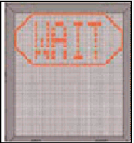 |
| 4.2.2 CAPTURE The floating arrows indicate that the system is activated and in capture mode, searching for an approaching aircraft. It shall be checked that the correct aircraft type is displayed. The lead-in line shall be followed. THE PILOT MUST NOT PROCEED BEYOND THE BRIDGE, UNLESS THE ARROWS HAVE BEEN SUPERSEDED BY THE CLOSING RATE BAR | 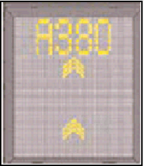 |
| 4.2.3 TRACKING When the aircraft has been caught by the laser, the floating arrow is replaced by the yellow centre line indicator. A flashing red arrow indicates the direction to turn. The vertical yellow arrow shows position in relation to the centre line. This indicator gives correct position and azimuth guidance. | |
| 4.2.4 CLOSING RATE Display of digital countdown will start when the aircraft is 20 meters from stop position. When the aircraft is less than 12 meters from the stop position, the closing rate is indicated by turning off one row of the centre line symbol per half a metre of the distance, covered by the aircraft toward the stop position of the stand. The picture illustrates the aircraft ten metres from stop position, slightly left of the centre line. The red arrow indicates the direction to steer. | 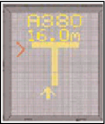 |
| 4.2.5 ALIGNED TO CENTRE The aircraft is eight meters from the stop position. The absence of any direction arrow indicates an aircraft on the centre line. | 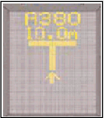 |
| 4.2.6 SLOW (DECREASE SPEED) Safedock is configured with a slowdown active zone (optional distances set from the stop position, standard 6 -24 M) according to an acceptable docking speed (optional max allowed speed, standard 2 M/S). Note: When 2 M/S is rounded down to a single digit, it is approximately 7 KM/H, 4 MPH or 3 kt. If the aircraft is approaching faster than the accepted speed, the system will show SLOW as a warning to the pilots. | .PNG) |
| 4.2.7 AZIMUTH GUIDANCE The aircraft is at the displayed distance from the stop-position. The yellow arrow indicates an aircraft to the right of the centre-line, and the red flashing arrow indicates the direction to turn. | 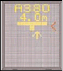 |
| 4.2.8 STOP POSITION REACHED When the correct stop-position is reached, the display will show STOP and red lights will be lit. | 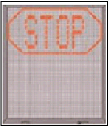 |
| 4.2.9 DOCKING COMPLETED When the aircraft has parked. OK will be displayed. | 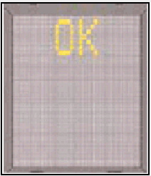 |
| 4.2.10 OVERSHOOT If the aircraft overshot the stop-position, TOO FAR will be displayed. | 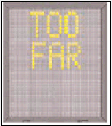 |
| 4.2.11 STOP SHORT If the aircraft is found standing still but has not reached the intended stop position, the message STOP OK will be shown after a pre-configured time. | 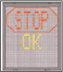 |
| 4.2.12 WAIT If some object is blocking the view toward approaching aircraft or the detected aircraft is lost during docking close to STOP, the display will show WAIT. The docking will continue as soon as the blocking object has disappeared or the system detects the aircraft again. THE PILOT MUST NOT PROCEED BEYOND THE BRIDGE, UNLESS THE "WAIT" MESSAGE HAS BEEN SUPERSEDED BY THE CLOSING RATE BAR. | 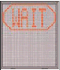 |
| 4.2.13 AIRCRAFT VERIFICATION FAILURE During entry into the Stand, the aircraft geometry is being checked. If, for any reason, aircraft verification is not made 12 M before the stop-position, the display will first show WAIT and make a second verification check. If this fails STOP and ID FAIL will be displayed. THE PILOT MUST NOT PROCEED BEYOND THE BRIDGE WITHOUT MANUAL GUIDANCE, UNLESS THE WAIT MESSAGE HAS BEEN SUPERSEDED BY THE CLOSING RATE BAR. |  |
| 4.2.14 SLOW (IN ABNORMAL SITUATIONS) This display can be shown for two reasons:
| .PNG) |
| 4.2.15 GATE BLOCKED If an object is found blocking the approach to gate / apron view from the Safedock to the planned stop position for the aircraft, the docking procedure will be halted with a WAIT and GATE BLOCK message. The docking procedure will resume as soon as the blocking object has been removed. THE PILOT MUST NOT PROCEED BEYOND THE BRIDGE WITHOUT MANUAL GUIDANCE, UNLESS THE WAIT MESSAGE HAS BEEN SUPERSEDED BY THE CLOSING RATE BAR. |  |
| 4.2.16 VIEW BLOCKED If the view towards the approaching aircraft is hindered, for example internally in the unit on the laser lens or on the laser window by dirt, or another obstacle in the closest view area, the Safedock will report a View blocked condition. Once the system is able to see the aircraft through the hinder, the message will be replaced with a closing rate display. THE PILOT MUST NOT PROCEED BEYOND THE BRIDGE WITHOUT MANUAL GUIDANCE, UNLESS THE WAIT MESSAGE HAS BEEN SUPERSEDED BY THE CLOSING RATE BAR. | 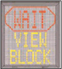 |
| 4.2.17 SBU-STOP Any unrecoverable error during the docking procedure will generate an SBU (safety back-up) condition. The display will show the text STOP SBU. A MANUAL BACKUP PROCEDURE MUST BE USED FOR DOCKING GUIDANCE. | 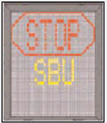 |
| 4.2.18 TOO FAST If the aircraft approaches with a speed higher than the docking system can handle, the message STOP TOO FAST will be displayed. The docking system must be re-started or the docking procedure completed by manual guidance. | 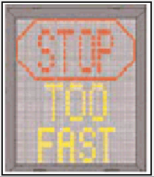 |
| 4.2.19 EMERGENCY STOP When the Emergency Stop button is pressed, STOP is displayed. | 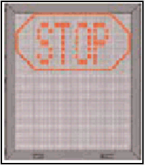 |
| 4.2.20 CHOCKS ON CHOCK ON will be displayed, when the ground staff has put the chocks in front of the nose wheel and pressed the " Chocks On" button on the Operator Panel. | 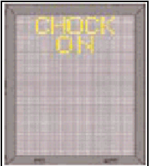 |
| 4.2.21 ERROR If a system error occurs, the message ERROR is displayed with an error code. The code is used for maintenance purposes and explained elsewhere. | 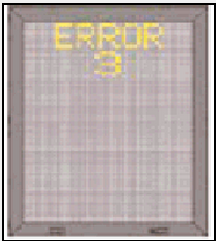 |
| 4.2.22 SYSTEM BREAKDOWN / POWER FAILURE In case of a severe system failure or power failure, the display will go black. A manual backup procedure must be used for docking guidance. |  |
OTHH AD 2.24 CHARTS RELATED TO AN AERODROME
AERODROME CHART - ICAO  |
AIRCRAFT PARKING / DOCKING CHART - ICAO |
AERODROME OBSTACLE CHART - ICAO RWY 16L/34R Type A |
AERODROME OBSTACLE CHART - ICAO RWY 16R/34L Type A |
PRECISION APPROACH TERRAIN CHART - ICAO RWY 16L |
PRECISION APPROACH TERRAIN CHART - ICAO RWY 34R |
PRECISION APPROACH TERRAIN CHART - ICAO RWY 16R |
PRECISION APPROACH TERRAIN CHART - ICAO RWY 34L |
SID - ICAO RWY 16L BATHA 1M RNAV |
SID - ICAO RWY 16L BUNDU 1M RNAV |
SID - ICAO RWY 16L ALSEM 1M / ALVEN 1M / NAMLA 1M RNAV |
SID - ICAO RWY 16L PATOM 1M RNAV |
SID - ICAO RWY 16L SALWA 1M RNAV |
SID - ICAO RWY 16L/R LOXUL 1C/1M |
SID - ICAO RWY 16R BATHA 1C RNAV |
SID - ICAO RWY 16R ALSEM 1C / BUNDU 1C / NAMLA 1C RNAV |
SID - ICAO RWY 16R ALVEN 1C / PATOM 1C RNAV |
SID - ICAO RWY 16R SALWA 1C RNAV |
SID - ICAO RWY 34L BATHA 1W RNAV |
SID - ICAO RWY 34L ALSEM 1W / BUNDU 1W / NAMLA 1W RNAV |
SID - ICAO RWY 34L ALVEN 1W / PATOM 1W RNAV |
SID - ICAO RWY 34L SALWA 1W RNAV |
SID - ICAO RWY 34L/R MUXOP 1E/1W |
SID - ICAO RWY 34R BATHA 1E / SALWA 1E RNAV |
SID - ICAO RWY 34R ALSEM 1E / BUNDU 1E / NAMLA 1E RNAV |
SID - ICAO RWY 34R ALVEN 1E / PATOM 1E RNAV |
STAR - ICAO RWY 16L AFNAN 1M / BAYAN 1M / GINTO 1M RNAV |
STAR - ICAO RWY 16R AFNAN 1C / BAYAN 1C / GINTO 1C RNAV |
STAR - ICAO RWY 34L AFNAN 1W / BAYAN 1W / GINTO 1W RNAV |
STAR - ICAO RWY 34R AFNAN 1E / BAYAN 1E / GINTO 1E RNAV |
ATC SURVEILLANCE MINIMUM ALTITUDE CHART - ICAO |
IAC - ICAO RWY 16L ILS |
IAC - ICAO RWY 16L VOR |
IAC - ICAO RWY 16L RNAV (GNSS) |
IAC - ICAO RWY 16R ILS |
IAC - ICAO RWY 16R VOR |
IAC - ICAO RWY 16R RNAV (GNSS) |
IAC - ICAO RWY 34L ILS |
IAC - ICAO RWY 34L VOR |
IAC - ICAO RWY 34L RNAV (GNSS) |
IAC - ICAO RWY 34R ILS |
IAC - ICAO RWY 34R VOR |
IAC - ICAO RWY 34R RNAV (GNSS) |
BIRD CONCENTRATIONS |