AD 2 Aerodromes
OTBD — DOHA INTERNATIONAL
OTBD AD 2.1 AERODROME LOCATION INDICATOR AND NAME
OTBD — DOHA INTERNATIONAL
OTBD AD 2.2 AERODROME GEOGRAPHICAL AND ADMINISTRATIVE DATA
| 1 | ARP coordinates and site at AD | 251539.81N 0513354.34E, Mid - point of RWY, on CL. | ||||||||||
| 2 | Direction and distance from (city) | 3.5 NM SE from Doha City Centre | ||||||||||
| 3 | Elevation/Reference temperature | 36.672 FT / 41° C | ||||||||||
| 4 | Geoid undulation at AD ELEV PSN | -98.188 FT | ||||||||||
| 5 | MAG VAR/Annual change | 2.29˚E (JAN 2014) / 0.05˚E | ||||||||||
| 6 | AD Administration, address, telephone, telefax, telex, AFS and website address |
| ||||||||||
| 7 | Types of traffic permitted (IFR/VFR) | IFR / VFR | ||||||||||
| 8 | Remarks | NIL |
OTBD AD 2.3 OPERATIONAL HOURS
| 1 | AD Operator | SUN-THU: 0400-1100 |
| 2 | Customs and immigration | H24 |
| 3 | Health and sanitation | H24 |
| 4 | AIS Briefing Office | H24 |
| 5 | ATS Reporting Office (ARO) | H24 |
| 6 | MET Briefing Office | H24 |
| 7 | ATS | H24 |
| 8 | Fuelling | H24 |
| 9 | Handling | H24, see GEN1.1.9 |
| 10 | Security | H24 |
| 11 | De-icing | Not required due to local climate |
| 12 | Remarks | NIL |
OTBD AD 2.4 HANDLING SERVICES AND FACILITIES
| 1 | Cargo-handling facilities | Available. Cranes by prior arrangement only. |
| 2 | Fuel/oil types | Fuel: Jet A1 AVGAS 100 available only at Qatar Aeronautical College (QAC). Oil: NIL. |
| 3 | Fuelling facilities/capacity | Hydrant system and bowsers on bays A13 to A18. All other bays bowsers only. |
| 4 | De-icing facilities | Not required due to local climate. |
| 5 | Hangar space for visiting aircraft | NIL |
| 6 | Repair facilities for visiting aircraft | Contact QAS, see GEN 1.1.9 |
| 7 | Remarks | For handling facilities / services contact QAS, see GEN 1.1.9 Every Sunday during 0600 - 0700, fuel line maintenance will take place adjacent to western edge of TWY D between aircraft stand A18 and intersection TWY E1. Maintenance will not take place during aircraft movements. |
OTBD AD 2.5 PASSENGER FACILITIES
| 1 | Hotels | Hotel accommodation available in Doha City. |
| 2 | Restaurants | H24 Airport restaurant in the terminal building |
| 3 | Transportation | Taxis and courtesy coaches to hotels |
| 4 | Medical facilities | Full medical facilities available in Doha |
| 5 | Bank and Post Office | Available at airport |
| 6 | Tourist Office | Available at airport |
| 7 | Remarks | NIL |
OTBD AD 2.6 RESCUE AND FIRE FIGHTING SERVICES
| 1 | AD category for fire fighting | CAT 9 with CAT 10 available on request |
| 2 | Rescue equipment | As per ICAO Annex 14 |
| 3 | Capability for removal of disabled aircraft | All aircraft types, Contact +974 44556789 |
| 4 | Remarks | Total number of trained personnel: 121 Communication with aircraft on ground available on 121.6 MHz |
OTBD AD 2.7 SEASONAL AVAILABILITY - CLEARING
| 1 | Types of clearing equipment | NIL |
| 2 | Clearance priorities | N/A |
| 3 | Remarks | Local climate precludes the requirement. Aerodrome is available in all seasons. |
OTBD AD 2.8 APRONS, TAXIWAYS AND CHECK LOCATIONS/POSITIONS DATA
| 1 | Designation, surface and strength of aprons | MAIN APRON: concrete, PCN 70 / R / A / X / T WESTERN APRON: concrete, PCN 70 / F/ A / X / U EASTERN APRON (1): concrete, PCN 70 / R / B / W / U EASTERN APRON (2) - (East of TWY D2 East): concrete, PCN 72 / R / B / W / T - (West of TWY D2 East): concrete, PCN 68 / R / B / W / T EASTERN APRON (3): concrete, PCN 70 / R / B / W / U EASTERN APRON (4): concrete, PCN 79 / R / A / W / T EASTERN APRON EXTENSION: concrete, PCN 63 / R / A / X / T RIZON APRON: asphalt, PCN 40 / F / B / X / U ISOLATED PARKING: concrete, PCN 68 / R / B / W / T |
| 2 | Designation, width, surface and strength of taxiways | TWY A: 34 M, asphalt, PCN 60 / F / A / X / T TWY C: 23 M, asphalt, PCN 60 / F / A / X / T TWY D: 23 M, asphalt, PCN 60 / F / A / X / T TWY F: 26 M, asphalt, PCN 60 / F / A / X / T TWY P: 33 M, asphalt, PCN 70 / F / A / X / T TWY B, TWY E1, TWY E2, TWY G: 29 M, asphalt, PCN 60 / F / A / X / T TWY B1, TWY C1, TWY D1, TWY D3, TWY D4: 29 M, asphalt, PCN 70 / F / A / X / U TWY D2, TWY D2 EAST, TWY V, TWY Z: 23 M, asphalt, PCN 72 / F / B / W / T TWY D2C: 18 M, asphalt, PCN 46 / F / B / W / U TWY U: 18 M, asphalt, PCN 40 / F / B / X / U TWY H, TWY J, TWY K, TWY L, TWY M, TWY N, TWY Q, TWY R, TWY S, TWY T, TWY Y: 23 M, asphalt, PCN 60 / F / A / X / T |
| 3 | Altimeter checkpoint location and elevation | MAIN APRON, 34 FT AMSL |
| 4 | VOR checkpoints | Holding point TWY A 335R DOH 2.56 NM Holding point TWY C 334R DOH 1.9 NM Holding point TWY G 329R DOH 0.55 NM |
| 5 | INS checkpoints | See ACFT PARKING / DOCKING CHART |
| 6 | Remarks | NIL |
OTBD AD 2.9 SURFACE MOVEMENT GUIDANCE AND CONTROL SYSTEM AND MARKINGS
| 1 | Use of aircraft stand ID signs, TWY guide lines and visual docking/parking guidance system at aircraft stands | Taxiing guidance signs at all intersections with TWY and RWY at all holding positions Visual Docking Guidance System (VDGS) installed and operational at bays A1 to A6, A9 to A18, E1 to E37 and W1 to W3, W6, W7, J1 and J2. Visual Docking Guidance System (VDGS) not provided for stands A1N, A1L, A2L, A2R, A3L, A3R, A4L, A4R, A5L, A5R, A6L, A6R, A10L, A10R, W1R, W2R, W3L, W3R, E1L, E1R, E2L, E2R, E6L, E6R, E7L, E7R, E9L, E9R, E10L, E10R, E13L, E13R, E14L, E14R, E15L, E15R, E16L, E16R, E17L, E17R, E18L, E18R, E19L, E19R, E20L, E20R, E21L, E21R, E22L, E22R, E23L, E23R, E24L, E24R, E27L, C1-C9 and Pilots to follow Marshallers instructions. For information on Visual Docking Guidance System (VDGS) see OTBD AD 2.23.1 Visual Docking Guidance System |
| 2 | RWY and TWY markings | RWY: designation, THR, displaced landing THR, TDZ, CL, edge, RWY end as appropriately marked TWY: Edge, CL, holding positions at all TWY / RWY intersections marked |
| 3 | Stop bars | Stop bars where appropriate. |
| 4 | Remarks | TWY G: RWY holding point CAT II hold markings only. No CAT I markings available. TWY D2C: Taxiing to/from stands will be via follow-me vehicle |
OTBD AD 2.10 AERODROME OBSTACLES
| In approach/TKOF areas | In circling area and at AD | |||||
|---|---|---|---|---|---|---|
| 1 | 2 | |||||
| OBST ID/ Designation | RWY/Area affected | OBST type ELEV, Marking/LGT | Coordinates | OBST ID/ Designation | OBST type ELEV, Marking/LGT | Coordinates |
| a | b | c | d | a | b | c |
| OT-1053 | 15 APCH | ANTENNA 29.99 M / 98.38 FT NIL / NIL | 251653.03N 0513311.10E | OT-1003 | ANTENNA 57.03 M / 187.10 FT NIL / NIL | 251615.75N 0513319.13E |
| OT-1430 | 15 APCH | BUILDING 177.16 M / 581.22 FT NIL / YES | 251916.80N 0513144.46E | OT-1006 | ANTENNA 55.28 M / 181.35 FT NIL / NIL | 251556.67N 0513309.17E |
| OT-1467 | 15 APCH | BUILDING 177.27 M / 581.58 FT NIL / YES | 251915.97N 0513144.92E | OT-1045 | ANTENNA 63.54 M / 208.45 FT NIL / NIL | 251711.95N 0513343.21E |
| OT-1505 | 15 APCH | BUILDING 211.21 M / 692.94 FT NIL / YES | 251935.18N 0513127.94E | OT-1067 | ANTENNA 55.60 M / 182.40 FT NIL / NIL | 251615.92N 0513319.37E |
| OT-5573 | 15 APCH | BUILDING 184.38 M / 604.92 FT NIL / NIL | 251948.90N 0513127.56E | OT-1443 | ANTENNA 86.75 M / 284.60 FT NIL / YES | 251906.25N 0513209.70E |
| OT-5574 | 15 APCH | BUILDING 187.16 M / 614.06 FT NIL / NIL | 251947.42N 0513129.14E | OT-1448 | ANTENNA 94.69 M / 310.65 FT NIL / YES | 251630.56N 0513145.42E |
| OT-5576 | 15 APCH | BUILDING 162.24 M / 532.28 FT NIL / NIL | 251941.84N 0513136.92E | OT-1449 | ANTENNA 82.87 M / 271.87 FT NIL / YES | 251655.69N 0513130.76E |
| OT-5577 | 15 APCH | BUILDING 226.05 M / 741.64 FT NIL / NIL | 251934.35N 0513128.68E | OT-1495 | ANTENNA 109.35 M / 358.75 FT NIL / YES | 251900.81N 0513130.98E |
| OT-5578 | 15 APCH | BUILDING 233.58 M / 766.33 FT NIL / NIL | 251931.39N 0513134.36E | OT-1064 | APRON_LIGHT 41.53 M / 136.24 FT NIL / YES | 251609.66N 0513327.27E |
| OT-5579 | 15 APCH | BUILDING 191.49 M / 628.25 FT NIL / NIL | 251930.32N 0513140.96E | OT-1065 | APRON_LIGHT 41.79 M / 137.09 FT NIL / YES | 251612.58N 0513325.98E |
| OT-5582 | 15 APCH | BUILDING 190.58 M / 625.25 FT NIL / NIL | 251927.02N 0513140.90E | OT-1066 | APRON_LIGHT 41.81 M / 137.16 FT NIL / YES | 251614.06N 0513325.34E |
| OT-5584 | 15 APCH | BUILDING 212.00 M / 695.52 FT NIL / NIL | 251918.41N 0513137.34E | OT-1068 | APRON_LIGHT 42.39 M / 139.06 FT NIL / YES | 251616.73N 0513324.17E |
| OT-5586 | 15 APCH | BUILDING 176.80 M / 580.05 FT NIL / NIL | 251915.07N 0513148.28E | OT-1069 | APRON_LIGHT 43.08 M / 141.33 FT NIL / YES | 251618.77N 0513323.22E |
| OT-5587 | 15 APCH | BUILDING 163.86 M / 537.61 FT NIL / NIL | 251911.45N 0513152.19E | OT-1070 | APRON_LIGHT 43.06 M / 141.26 FT NIL / YES | 251620.96N 0513322.27E |
| OT-5588 | 15 APCH | BUILDING 195.18 M / 640.35 FT NIL / NIL | 251910.09N 0513145.29E | OT-1071 | APRON_LIGHT 42.19 M / 138.41 FT NIL / YES | 251622.89N 0513321.54E |
| OT-2051 | 15 APCH | BUILDING(L) 232.92 M / 764.18 FT NIL / YES | 251931.62N 0513133.45E | OT-1074 | APRON_LIGHT 35.61 M / 116.82 FT NIL / YES | 251536.64N 0513341.84E |
| OT-4900 | 15 APCH | BUILDING(L) 232.90 M / 764.10 FT NIL / YES | 251932.71N 0513135.22E | OT-1075 | APRON_LIGHT 35.89 M / 117.74 FT NIL / YES | 251538.83N 0513340.88E |
| OT-4901 | 15 APCH | BUILDING(L) 233.01 M / 764.47 FT NIL / YES | 251932.69N 0513134.32E | OT-1077 | APRON_LIGHT 36.65 M / 120.23 FT NIL / YES | 251541.06N 0513339.92E |
| OT-2072 | 15 APCH | BUILDING(U/C) 182.63 M / 599.19 FT NIL / YES | 251948.89N 0513131.21E | OT-1078 | APRON_LIGHT 37.34 M / 122.49 FT NIL / YES | 251543.24N 0513338.96E |
| OT-4902 | 15 APCH | BUILDING_HOIST 224.87 M / 737.75 FT NIL / YES | 251934.47N 0513127.60E | OT-1079 | APRON_LIGHT 38.18 M / 125.25 FT NIL / YES | 251545.36N 0513338.01E |
| OT-5581 | 15 APCH | BUILDING_U/C 171.18 M / 561.61 FT NIL / NIL | 251927.86N 0513133.47E | OT-1080 | APRON_LIGHT 38.49 M / 126.27 FT NIL / YES | 251547.33N 0513337.13E |
| OT-5500 | 15 APCH | CRANE(TEMP) 57.99 M / 190.26 FT NIL / NIL | 251711.29N 0513259.81E | OT-1081 | APRON_LIGHT 35.94 M / 117.90 FT NIL / YES | 251549.95N 0513336.76E |
| OT-5502 | 15 APCH | CRANE(TEMP) 45.82 M / 150.34 FT NIL / NIL | 251713.01N 0513300.59E | OT-1082 | APRON_LIGHT 36.76 M / 120.59 FT NIL / YES | 251551.70N 0513336.25E |
| OT-5503 | 15 APCH | CRANE(TEMP) 53.81 M / 176.54 FT NIL / NIL | 251715.02N 0513256.94E | OT-1083 | APRON_LIGHT 37.43 M / 122.79 FT NIL / YES | 251553.44N 0513335.44E |
| OT-5504 | 15 APCH | CRANE(TEMP) 80.66 M / 264.64 FT NIL / NIL | 251714.66N 0513259.92E | OT-1085 | APRON_LIGHT 37.85 M / 124.17 FT NIL / YES | 251555.04N 0513334.75E |
| OT-5560 | 15 APCH | CRANE(TEMP) 167.27 M / 548.80 FT NIL / NIL | 252313.45N 0513124.32E | OT-1086 | APRON_LIGHT 35.02 M / 114.88 FT NIL / YES | 251558.11N 0513334.12E |
| OT-5580 | 15 APCH | CRANE(TEMP) 233.04 M / 764.56 FT NIL / NIL | 251927.31N 0513136.66E | OT-1087 | APRON_LIGHT 35.12 M / 115.21 FT NIL / YES | 251559.12N 0513333.66E |
| OT-5505 | 15 APCH | JIB 68.18 M / 223.70 FT NIL / NIL | 251712.51N 0513259.72E | OT-1088 | APRON_LIGHT 35.40 M / 116.13 FT NIL / YES | 251600.28N 0513333.13E |
| OT-5606 | 15 APCH | STREETLIGHT 39.03 M / 128.06 FT NIL / NIL | 251701.33N 0513327.69E | OT-1089 | APRON_LIGHT 35.64 M / 116.92 FT NIL / YES | 251601.49N 0513332.63E |
| OT-1483 | 15 APCH / 33 TKOF | BUILDING 157.45 M / 516.56 FT NIL / YES | 251927.61N 0513208.93E | OT-1362 | ASPIRE_TOWER 319.28 M / 1047.50 FT NIL / YES | 251545.63N 0512640.65E |
| OT-1489 | 15 APCH / 33 TKOF | BUILDING 158.14 M / 518.82 FT NIL / YES | 251923.77N 0513215.45E | OT-1105 | ATC 39.41 M / 129.29 FT NIL / NIL | 251529.66N 0513343.94E |
| OT-1496 | 15 APCH / 33 TKOF | BUILDING 191.92 M / 629.65 FT NIL / YES | 251947.79N 0513201.43E | OT-2035 | ATC_RADAR 41.16 M / 135.04 FT NIL / NIL | 251529.64N 0513343.87E |
| OT-5562 | 15 APCH / 33 TKOF | BUILDING 256.10 M / 840.22 FT NIL / NIL | 251943.66N 0513150.88E | OT-1007 | BUILDING 64.97 M / 213.14 FT NIL / NIL | 251601.79N 0513302.80E |
| OT-5563 | 15 APCH / 33 TKOF | BUILDING 256.12 M / 840.27 FT NIL / NIL | 251943.68N 0513152.51E | OT-1009 | BUILDING 69.71 M / 228.69 FT NIL / YES | 251604.99N 0513256.60E |
| OT-5583 | 15 APCH / 33 TKOF | BUILDING 194.97 M / 639.67 FT NIL / NIL | 251927.32N 0513159.90E | OT-1022 | BUILDING 62.44 M / 204.84 FT NIL / NIL | 251706.96N 0513240.71E |
| OT-4886 | 15 APCH / 33 TKOF | BUILDING(L) 255.82 M / 839.30 FT NIL / YES | 251942.60N 0513149.94E | OT-1023 | BUILDING 72.02 M / 236.28 FT NIL / YES | 251708.08N 0513249.27E |
| OT-4887 | 15 APCH / 33 TKOF | BUILDING(L) 255.58 M / 838.52 FT NIL / YES | 251942.56N 0513151.55E | OT-1025 | BUILDING 80.02 M / 262.52 FT NIL / YES | 251711.18N 0513249.79E |
| OT-4892 | 15 APCH / 33 TKOF | BUILDING(L) 255.87 M / 839.47 FT NIL / YES | 251942.20N 0513150.87E | OT-1026 | BUILDING 72.34 M / 237.32 FT NIL / YES | 251715.81N 0513234.57E |
| OT-2070 | 15 APCH / 33 TKOF | CRANE(TEMP) 206.91 M / 678.84 FT NIL / YES | 251937.04N 0513153.29E | OT-1028 | BUILDING 76.78 M / 251.89 FT NIL / YES | 251721.09N 0513234.70E |
| OT-2071 | 15 APCH / 33 TKOF | CRANE(TEMP) 223.78 M / 734.19 FT NIL / YES | 251936.64N 0513152.18E | OT-1031 | BUILDING 73.02 M / 239.56 FT NIL / YES | 251718.62N 0513245.70E |
| OT-1480 | 33 TKOF | BUILDING 138.01 M / 452.78 FT NIL / YES | 251931.29N 0513204.17E | OT-1034 | BUILDING 82.47 M / 270.56 FT NIL / YES | 251720.93N 0513247.46E |
| OT-1482 | 33 TKOF | BUILDING 117.97 M / 387.03 FT NIL / YES | 251929.58N 0513206.50E | OT-1371 | BUILDING 83.17 M / 272.86 FT NIL / YES | 251711.67N 0513249.99E |
| OT-1485 | 33 TKOF | BUILDING 142.82 M / 468.56 FT NIL / YES | 251937.69N 0513215.05E | OT-1372 | BUILDING 80.01 M / 262.49 FT NIL / YES | 251712.14N 0513249.71E |
| OT-1497 | 33 TKOF | BUILDING 146.95 M / 482.11 FT NIL / YES | 251945.70N 0513208.27E | OT-1373 | BUILDING 81.28 M / 266.65 FT NIL / YES | 251721.14N 0513247.91E |
| OT-1038 | 33 TKOF | CCTV 18.02 M / 59.11 FT NIL / NIL | 251659.11N 0513318.21E | OT-1374 | BUILDING 83.03 M / 272.40 FT NIL / YES | 251721.89N 0513247.36E |
| OT-2004 | 33 TKOF | COMMS_MAST 25.37 M / 83.24 FT NIL / NIL | 251704.74N 0513313.75E | OT-1375 | BUILDING 63.57 M / 208.55 FT NIL / NIL | 251714.35N 0513237.83E |
| OT-1036 | 33 TKOF | LAMPPOST 18.14 M / 59.50 FT NIL / NIL | 251659.08N 0513316.30E | OT-1376 | BUILDING 69.55 M / 228.17 FT NIL / YES | 251719.45N 0513237.81E |
| OT-1037 | 33 TKOF | LAMPPOST 18.24 M / 59.83 FT NIL / NIL | 251659.12N 0513317.70E | OT-1377 | BUILDING 77.99 M / 255.86 FT NIL / YES | 251721.04N 0513237.66E |
| OT-1039 | 33 TKOF | LAMPPOST 18.40 M / 60.35 FT NIL / NIL | 251659.11N 0513318.70E | OT-1379 | BUILDING 54.76 M / 179.65 FT NIL / NIL | 251728.32N 0513242.60E |
| OT-1040 | 33 TKOF | LAMPPOST 18.97 M / 62.22 FT NIL / NIL | 251659.02N 0513320.75E | OT-1382 | BUILDING 54.48 M / 178.73 FT NIL / NIL | 251728.81N 0513242.20E |
| OT-1041 | 33 TKOF | LAMPPOST 18.67 M / 61.24 FT NIL / NIL | 251658.74N 0513321.51E | OT-1385 | BUILDING 79.49 M / 260.78 FT NIL / YES | 251724.48N 0513237.09E |
| OT-1042 | 33 TKOF | LAMPPOST 18.59 M / 60.98 FT NIL / NIL | 251657.98N 0513322.74E | OT-1386 | BUILDING 75.64 M / 248.15 FT NIL / YES | 251724.51N 0513233.66E |
| OT-1043 | 33 TKOF | LAMPPOST 18.47 M / 60.58 FT NIL / NIL | 251657.23N 0513323.74E | OT-1387 | BUILDING 62.66 M / 205.57 FT NIL / NIL | 251722.82N 0513233.22E |
| OT-2005 | 33 TKOF | LAMPPOST 18.43 M / 60.46 FT NIL / NIL | 251700.24N 0513318.64E | OT-1388 | BUILDING 69.99 M / 229.61 FT NIL / YES | 251720.77N 0513234.14E |
| OT-2006 | 33 TKOF | LAMPPOST 17.87 M / 58.63 FT NIL / NIL | 251701.23N 0513319.23E | OT-1389 | BUILDING 69.47 M / 227.91 FT NIL / YES | 251716.90N 0513234.40E |
| OT-2007 | 33 TKOF | LAMPPOST 18.23 M / 59.80 FT NIL / NIL | 251700.20N 0513319.95E | OT-1390 | BUILDING 63.51 M / 208.35 FT NIL / NIL | 251714.40N 0513236.86E |
| OT-2036 | 33 TKOF | SELEX_MAST 18.20 M / 59.70 FT NIL / NIL | 251657.79N 0513317.65E | OT-1391 | BUILDING 79.46 M / 260.68 FT NIL / YES | 251713.41N 0513229.51E |
| OT-1253 | 33 APCH | LAMPPOST 31.18 M / 102.28 FT NIL / NIL | 251353.32N 0513433.03E | OT-1392 | BUILDING 57.96 M / 190.14 FT NIL / NIL | 251725.33N 0513227.94E |
| OT-1254 | 33 APCH | LAMPPOST 33.10 M / 108.58 FT NIL / NIL | 251355.48N 0513432.10E | OT-1393 | BUILDING 77.38 M / 253.86 FT NIL / YES | 251721.03N 0513223.52E |
| OT-1255 | 33 APCH | LAMPPOST 33.17 M / 108.81 FT NIL / NIL | 251357.56N 0513431.00E | OT-1395 | BUILDING 81.66 M / 267.90 FT NIL / YES | 251719.66N 0513209.09E |
| OT-1256 | 33 APCH | LAMPPOST 33.21 M / 108.95 FT NIL / NIL | 251359.79N 0513429.82E | OT-1400 | BUILDING 62.53 M / 205.14 FT NIL / NIL | 251728.37N 0513137.21E |
| OT-1257 | 33 APCH | LAMPPOST 33.27 M / 109.14 FT NIL / NIL | 251401.33N 0513428.98E | OT-1402 | BUILDING 63.46 M / 208.19 FT NIL / NIL | 251743.27N 0513221.09E |
| OT-1258 | 33 APCH | LAMPPOST 33.37 M / 109.47 FT NIL / NIL | 251403.39N 0513427.88E | OT-1403 | BUILDING 150.00 M / 492.12 FT NIL / YES | 251847.71N 0513104.91E |
| OT-1259 | 33 APCH | LAMPPOST 33.50 M / 109.90 FT NIL / NIL | 251405.42N 0513426.80E | OT-1404 | BUILDING 122.99 M / 403.50 FT NIL / YES | 251848.71N 0513106.29E |
| OT-1260 | 33 APCH | LAMPPOST 33.55 M / 110.06 FT NIL / NIL | 251407.46N 0513425.71E | OT-1405 | BUILDING 116.29 M / 381.52 FT NIL / YES | 251846.24N 0513108.52E |
| OT-1609 | 33 APCH | WINDSLEEVE 14.80 M / 48.55 FT NIL / YES | 251427.62N 0513422.69E | OT-1406 | BUILDING 114.30 M / 374.99 FT NIL / YES | 251846.01N 0513107.80E |
| OT-1623 | 15 TKOF | 15_LLZ_L/H 10.64 M / 34.92 FT NIL / YES | 251418.95N 0513429.09E | OT-1407 | BUILDING 114.13 M / 374.43 FT NIL / YES | 251847.38N 0513110.03E |
| OT-1625 | 15 TKOF | 15_LLZ_MID 10.65 M / 34.93 FT NIL / NIL | 251419.23N 0513429.87E | OT-1409 | BUILDING 139.12 M / 456.42 FT NIL / YES | 251904.11N 0513114.66E |
| OT-1621 | 15 TKOF | 15_LLZ_NFM 9.97 M / 32.72 FT NIL / NIL | 251421.54N 0513428.87E | OT-1410 | BUILDING 144.69 M / 474.69 FT NIL / YES | 251907.68N 0513116.45E |
| OT-1624 | 15 TKOF | 15_LLZ_R/H 10.65 M / 34.95 FT NIL / YES | 251419.51N 0513430.64E | OT-1412 | BUILDING 142.17 M / 466.43 FT NIL / YES | 251906.27N 0513118.25E |
| OT-2033 | 15 TKOF | SELEX_MAST 13.65 M / 44.80 FT NIL / NIL | 251418.02N 0513427.55E | OT-1413 | BUILDING 157.48 M / 516.66 FT NIL / YES | 251907.15N 0513120.34E |
| OT-1414 | BUILDING 125.63 M / 412.16 FT NIL / YES | 251906.43N 0513125.26E | ||||
| OT-1416 | BUILDING 123.73 M / 405.93 FT NIL / YES | 251909.13N 0513129.75E | ||||
| OT-1422 | BUILDING 216.60 M / 710.62 FT NIL / YES | 251917.58N 0513137.02E | ||||
| OT-1423 | BUILDING 212.49 M / 697.14 FT NIL / YES | 251916.39N 0513137.50E | ||||
| OT-1438 | BUILDING 111.44 M / 365.60 FT NIL / YES | 251931.14N 0513216.28E | ||||
| OT-1446 | BUILDING 62.86 M / 206.22 FT NIL / NIL | 251743.47N 0513220.64E | ||||
| OT-1447 | BUILDING 68.59 M / 225.02 FT NIL / NIL | 251659.38N 0513140.55E | ||||
| OT-1450 | BUILDING 74.38 M / 244.02 FT NIL / YES | 251730.31N 0513115.34E | ||||
| OT-1451 | BUILDING 71.21 M / 233.62 FT NIL / YES | 251645.31N 0513114.40E | ||||
| OT-1453 | BUILDING 58.29 M / 191.23 FT NIL / NIL | 251714.06N 0513107.60E | ||||
| OT-1455 | BUILDING 102.70 M / 336.93 FT NIL / YES | 251647.69N 0513029.72E | ||||
| OT-1515 | BUILDING 146.92 M / 482.01 FT NIL / YES | 252239.52N 0513133.46E | ||||
| OT-2150 | BUILDING 71.56 M / 234.77 FT NIL / YES | 251551.93N 0513133.83E | ||||
| OT-4880 | BUILDING 83.12 M / 272.69 FT NIL / YES | 251712.00N 0513248.92E | ||||
| OT-5508 | BUILDING 92.84 M / 304.59 FT NIL / NIL | 251629.66N 0513033.81E | ||||
| OT-5509 | BUILDING 124.69 M / 409.09 FT NIL / NIL | 251650.81N 0513027.87E | ||||
| OT-5510 | BUILDING 65.42 M / 214.62 FT NIL / NIL | 251553.50N 0513133.39E | ||||
| OT-5511 | BUILDING 65.56 M / 215.08 FT NIL / NIL | 251550.63N 0513133.32E | ||||
| OT-5589 | BUILDING 200.95 M / 659.28 FT NIL / NIL | 251910.37N 0513140.56E | ||||
| OT-5590 | BUILDING 200.86 M / 658.98 FT NIL / NIL | 251908.61N 0513140.23E | ||||
| OT-5591 | BUILDING 170.49 M / 559.34 FT NIL / NIL | 251911.40N 0513120.38E | ||||
| OT-5599 | BUILDING 121.52 M / 398.70 FT NIL / NIL | 251711.91N 0513023.39E | ||||
| OT-4883 | BUILDING(L) 249.07 M / 817.16 FT NIL / YES | 251905.43N 0513133.64E | ||||
| OT-4888 | BUILDING(L) 248.19 M / 814.27 FT NIL / YES | 251905.23N 0513137.83E | ||||
| OT-4889 | BUILDING(L) 248.28 M / 814.57 FT NIL / YES | 251905.65N 0513138.58E | ||||
| OT-2000 | BUILDING_ANTENNA 78.05 M / 256.06 FT NIL / YES | 251623.72N 0513240.55E | ||||
| OT-5593 | BUILDING_U/C 154.28 M / 506.17 FT NIL / NIL | 251904.17N 0513110.85E | ||||
| OT-5595 | BUILDING_U/C 142.77 M / 468.40 FT NIL / NIL | 251904.11N 0513108.32E | ||||
| OT-5597 | BUILDING_U/C 217.89 M / 714.85 FT NIL / NIL | 251858.36N 0513108.39E | ||||
| OT-1363 | COMMS_MAST 168.71 M / 553.50 FT NIL / YES | 251705.27N 0512749.93E | ||||
| OT-1364 | COMMS_MAST 201.70 M / 661.74 FT NIL / YES | 251656.61N 0512816.23E | ||||
| OT-5939 | COMMS_MAST 53.95 M / 176.99 FT NIL / NIL | 251714.31N 0513356.58E | ||||
| OT-2030 | CRANE(TEMP) 59.98 M / 196.79 FT NIL / YES | 251607.42N 0513307.79E | ||||
| OT-5501 | CRANE(TEMP) 70.99 M / 232.89 FT NIL / YES | 251712.12N 0513257.51E | ||||
| OT-5559 | CRANE(TEMP) 155.05 M / 508.68 FT NIL / NIL | 252237.92N 0513124.44E | ||||
| OT-5592 | CRANE(TEMP) 178.99 M / 587.22 FT NIL / NIL | 251904.71N 0513110.40E | ||||
| OT-5594 | CRANE(TEMP) 200.57 M / 658.04 FT NIL / NIL | 251904.85N 0513107.96E | ||||
| OT-5596 | CRANE(TEMP) 241.70 M / 792.99 FT NIL / NIL | 251858.48N 0513107.74E | ||||
| OT-5598 | CRANE(TEMP) 161.37 M / 529.42 FT NIL / NIL | 251857.69N 0513105.18E | ||||
| OT-1380 | DOCK_CRANE 65.15 M / 213.74 FT NIL / YES | 251808.56N 0513310.17E | ||||
| OT-1381 | DOCK_CRANE 54.25 M / 177.97 FT NIL / NIL | 251752.67N 0513317.28E | ||||
| OT-1027 | FLAG-POLE 68.53 M / 224.82 FT NIL / NIL | 251714.53N 0513246.35E | ||||
| OT-5512 | FLOODLIGHT 79.34 M / 260.29 FT NIL / NIL | 251533.72N 0513111.16E | ||||
| OT-5513 | FLOODLIGHT 79.54 M / 260.96 FT NIL / NIL | 251533.76N 0513116.54E | ||||
| OT-5514 | FLOODLIGHT 79.51 M / 260.85 FT NIL / NIL | 251528.65N 0513116.54E | ||||
| OT-5515 | FLOODLIGHT 79.32 M / 260.24 FT NIL / NIL | 251527.82N 0513111.85E | ||||
| OT-1109 | HANGAR 37.15 M / 121.87 FT NIL / YES | 251511.28N 0513421.06E | ||||
| OT-1134 | LAMPPOST 33.12 M / 108.65 FT NIL / NIL | 251429.55N 0513413.92E | ||||
| OT-1135 | LAMPPOST 33.56 M / 110.09 FT NIL / NIL | 251431.63N 0513412.83E | ||||
| OT-1136 | LAMPPOST 34.02 M / 111.60 FT NIL / NIL | 251433.58N 0513411.79E | ||||
| OT-1137 | LAMPPOST 34.15 M / 112.03 FT NIL / NIL | 251435.69N 0513410.67E | ||||
| OT-1138 | LAMPPOST 34.71 M / 113.87 FT NIL / NIL | 251437.75N 0513409.57E | ||||
| OT-1139 | LAMPPOST 34.66 M / 113.70 FT NIL / NIL | 251440.02N 0513409.44E | ||||
| OT-1140 | LAMPPOST 34.90 M / 114.49 FT NIL / NIL | 251441.48N 0513408.66E | ||||
| OT-1142 | LAMPPOST 35.04 M / 114.95 FT NIL / NIL | 251442.94N 0513407.86E | ||||
| OT-1145 | LAMPPOST 35.34 M / 115.93 FT NIL / NIL | 251444.47N 0513406.92E | ||||
| OT-1146 | LAMPPOST 40.59 M / 133.16 FT NIL / NIL | 251443.06N 0513405.71E | ||||
| OT-1147 | LAMPPOST 35.26 M / 115.67 FT NIL / NIL | 251446.03N 0513406.21E | ||||
| OT-1149 | LAMPPOST 40.23 M / 131.98 FT NIL / NIL | 251444.48N 0513405.10E | ||||
| OT-1153 | LAMPPOST 35.25 M / 115.64 FT NIL / NIL | 251447.50N 0513405.43E | ||||
| OT-1159 | LAMPPOST 34.99 M / 114.79 FT NIL / NIL | 251448.97N 0513404.65E | ||||
| OT-1163 | LAMPPOST 34.54 M / 113.31 FT NIL / NIL | 251450.38N 0513403.86E | ||||
| OT-1261 | LAMPPOST 33.48 M / 109.83 FT NIL / NIL | 251409.25N 0513424.76E | ||||
| OT-1262 | LAMPPOST 33.25 M / 109.07 FT NIL / NIL | 251411.25N 0513423.71E | ||||
| OT-1263 | LAMPPOST 33.52 M / 109.96 FT NIL / NIL | 251413.40N 0513422.56E | ||||
| OT-1264 | LAMPPOST 33.25 M / 109.07 FT NIL / NIL | 251415.23N 0513421.58E | ||||
| OT-1265 | LAMPPOST 33.27 M / 109.14 FT NIL / NIL | 251417.30N 0513420.47E | ||||
| OT-1266 | LAMPPOST 33.33 M / 109.34 FT NIL / NIL | 251419.34N 0513419.39E | ||||
| OT-1268 | LAMPPOST 33.59 M / 110.19 FT NIL / NIL | 251421.36N 0513418.29E | ||||
| OT-1270 | LAMPPOST 33.52 M / 109.96 FT NIL / NIL | 251423.50N 0513417.15E | ||||
| OT-1271 | LAMPPOST 33.26 M / 109.11 FT NIL / NIL | 251425.47N 0513416.11E | ||||
| OT-1272 | LAMPPOST 33.44 M / 109.70 FT NIL / NIL | 251427.52N 0513415.03E | ||||
| OT-2016 | MARRIOT_HOTEL 53.98 M / 177.09 FT NIL / NIL | 251712.10N 0513342.59E | ||||
| OT-4882 | MARRIOT_HOTEL 53.94 M / 176.95 FT NIL / YES | 251711.28N 0513343.77E | ||||
| OT-5569 | MAST 182.31 M / 598.12 FT NIL / NIL | 251844.29N 0513011.39E | ||||
| OT-1018 | MINORETTE 51.31 M / 168.33 FT NIL / NIL | 251655.26N 0513304.72E | ||||
| OT-4241 | RADAR_LC 98.06 M / 321.71 FT NIL / YES | 251629.28N 0513632.75E | ||||
| OT-1508 | SAT-DISH 140.74 M / 461.74 FT NIL / YES | 251907.79N 0513115.62E | ||||
| OT-2037 | SELEX_MAST 18.01 M / 59.09 FT NIL / NIL | 251651.94N 0513329.71E | ||||
| OT-5605 | STREETLIGHT 39.67 M / 130.15 FT NIL / NIL | 251701.64N 0513331.01E | ||||
| OT-2057 | Building Spire (L) 234.71 M / 770.03 FT NIL / YES | 251903.07N 0513141.46E | ||||
OTBD AD 2.11 METEOROLOGICAL INFORMATION PROVIDED
| 1 | Associated MET Office | DOHA MET OFFICE |
| 2 | Hours of service | H24 |
| MET Office outside hours | NIL | |
| 3 | Office responsible for TAF preparation | DOHA MET OFFICE |
| Periods of validity | 24 HR | |
| 4 | Type forecast | TREND |
| Interval of issuance | ½ HR | |
| 5 | Briefing/consultation provided | Personal consultation, partial self briefing, telephone to forecaster |
| 6 | Flight documentation | Charts, abbreviated plain language text |
| Language(s) used | English | |
| 7 | Charts and other information available for briefing or consultation | S, U25, P25, (other levels on request), T, SWH (East & West), SWM (MID), TB (Gulf sector winds) |
| 8 | Supplementary equipment available for providing information | Telefax |
| 9 | ATS units provided with information | DOHA TOWER, DOHA APPROACH |
| 10 | Additional information (limitation of service, etc.) | NIL |
OTBD AD 2.12 RUNWAY PHYSICAL CHARACTERISTICS
| Designations RWY NR | TRUE & MAG BRG | Dimensions of RWY (M) | Strength (PCN) and surface of RWY and SWY | THR coordinates, RWY end coordinates, THR geoid undulation | THR elevation and highest elevation of TDZ of precision ARP RWY |
|---|---|---|---|---|---|
| 1 | 2 | 3 | 4 | 5 | 6 |
| 15 | 158.24˚T / 155.95˚M | 4 570 x 46 | 60 / F / A / X / T asphalt | 251626.1293N 0513333.9200E 251430.8845N 0513424.7309E -98.226 FT | THR 34.742 FT TDZ 10.95 M |
| 33 | 338.24˚ T/ 335.95˚M | 4 570 x 46 | 60 / F / A / X / T asphalt | 251430.8845N 0513424.7309E 251648.7426N 0513323.9466E -98.426 FT | THR 26.969 FT TDZ 7.90 M |
| Designations RWY NR | Slope of RWY- SWY | SWY dimensions (M) | CWY dimensions (M) | Strip dimensions (M) | OFZ | Remarks | |
|---|---|---|---|---|---|---|---|
| RWY | SWY | ||||||
| 1 | 7 | 8 | 9 | 10 | 11 | 12 | |
| 15 | 0.11% first 1 524 M then 0.62% next 762 M then 0.00% next 914 M then 0.48% next 427 M then 0.15% next 945 M | NIL | NIL | 274 x 150 | 4 690 x 300 | Yes | Non load bearing shoulders 15 M |
| 33 | 0.15% first 945 M then 0.48% next 427 M then 0.00% next 914 M then 0.62% next 762 M then 0.11% next 1 524 M | NIL | NIL | 183 x 150 | 4 690 x 300 | Yes | Non load bearing shoulders 15 M |
OTBD AD 2.13 DECLARED DISTANCES
| RWY Designator | Intersection Departures | TORA (M) | TODA (M) | ASDA (M) | LDA (M) | Remarks |
|---|---|---|---|---|---|---|
| 1 | 2 | 3 | 4 | 5 | 6 | 7 |
| 15 | Not applicable | 4 570 | 4 844 | 4 570 | 3 820 | Threshold Displacement 750 M |
| TWY A | 3 821 | 4 095 | 3 821 | Not applicable | NIL | |
| TWY B | 3 058 | 3 332 | 3 058 | Not applicable | ||
| TWY B1 | 3 058 | 3 332 | 3 058 | Not applicable | ||
| TWY C1 | 2 516 | 2 790 | 2 516 | Not applicable | ||
| TWY C | 2 490 | 2 764 | 2 490 | Not applicable | ||
| TWY P | 2 451 | 2 725 | 2 451 | Not applicable | ||
| TWY E1 | 1 144 | 1 418 | 1 144 | Not applicable | ||
| TWY N | 1 144 | 1 418 | 1 144 | Not applicable | ||
| TWY E2 | 706 | 980 | 706 | Not applicable | ||
| TWY M | 706 | 980 | 706 | Not applicable | ||
| 33 | Not applicable | 4 570 | 4 753 | 4 570 | 4 570 | NIL |
| TWY F | 4 126 | 4 309 | 4 126 | Not applicable | ||
| TWY L | 4 126 | 4 309 | 4 126 | Not applicable | ||
| TWY K | 4 024 | 4 207 | 4 024 | Not applicable | ||
| TWY E2 | 3 890 | 4 073 | 3 890 | Not applicable | ||
| TWY M | 3 890 | 4 073 | 3 890 | Not applicable | ||
| TWY E1 | 3 450 | 3 633 | 3 450 | Not applicable | ||
| TWY N | 3 450 | 3 633 | 3 450 | Not applicable | ||
| LOOP | 2 482 | 2 665 | 2 482 | Not applicable | ||
| TWY C | 2 145 | 2 328 | 2 145 | Not applicable | ||
| TWY P | 2 145 | 2 328 | 2 145 | Not applicable | ||
| TWY B | 1 542 | 1 725 | 1 542 | Not applicable | ||
| TWY B1 | 1 542 | 1 725 | 1 542 | Not applicable | ||
| TWY A | 818 | 1 001 | 818 | Not applicable | ||
Note: Intersection departures are allowed subject to the following: | ||||||
OTBD AD 2.14 APPROACH AND RUNWAY LIGHTING
| RWY Designator | APCH LGT type, LEN, INTST | THR LGT, colour, WBAR | VASIS (MEHT) PAPI | TDZ LGT LEN | RWY Centre Line LGT Length, spacing, colour, INTST |
|---|---|---|---|---|---|
| 1 | 2 | 3 | 4 | 5 | 6 |
| 15 | ICAO CAT I precision approach lighting system 900 M LIH | Green supplemented by green WBAR | PAPI 3.5˚ (73.4 FT) | NIL | Length: 4 570 M Spacing: 30 M Colour: fm 0 M to last 900 M White, last 900 M to last 300 M Red / White, last 300 M Red INTST: LIH |
| 33 | ICAO CAT II and III precision approach lighting system 900 M LIH | Green supplemented by green WBAR | PAPI 3˚ (65.7 FT) | 900 M | Length: 4 570 M Spacing: 30 M Colour: fm 0 M to last 900 M White, last 900 M to last 300 M Red / White, last 300 M Red INTST: LIH |
| RWY Designator | RWY edge LGT LEN, spacing, colour, INTST | RWY End LGT colour, WBAR | SWY LGT LEN, colour | Remarks |
|---|---|---|---|---|
| 1 | 7 | 8 | 9 | 10 |
| 15 | Length: 4 570 M Spacing: 60 M Colour: fm 0 M to last 750 M Red, last 750 M to last 600 M White, last 600 M Amber INTST: LIH | Red NIL | NIL | On full length departures, the first 750 M of edge lights are Red due to DTHR |
| 33 | Length: 4 570 M Spacing: 60 M Colour: fm 0 M to last 600 M White, last 600 M Amber INTST: LIH | Red NIL | NIL | NIL |
OTBD AD 2.15 OTHER LIGHTING, SECONDARY POWER SUPPLY
| 1 | ABN /IBN location, characteristics and hours of operation | ABN: NIL IBN: NIL |
| 2 | LDI location and LGT | LDI: NIL |
| Anemometer location and LGT | Anemometer: Located APRX at 117 M west of RCL ABM start of RWY 15 and 268 M east of RCL ABM turning pad in the middle of the RWY; Lighted. | |
| 3 | TWY edge and centre line lighting | Edge: All taxiway edge-Blue. Centre line: Green. |
| 4 | Secondary power supply/switch-over time | Secondary power for CAT I / II / III Ops - on UPS immediate power and with battery backup for up to 30 minutes. Backup generator also available. Other lightings on backup generator. Switch-over time: Switch over time within 15 seconds. |
| 5 | Remarks | Blue - Apron edge lights. |
OTBD AD 2.16 HELICOPTER LANDING AREA
| 1 | Coordinates TLOF or THR of FATO Geoid undulation. | TLOF: | 251628.1676N 0513339.5089E | GUND: -98.230 FT | |
| FATO THR 15: | 251649.2306N 0513330.1857E | GUND: -98.194 FT | |||
| FATO THR 33: | 251625.1683N 0513340.8359E | GUND: -98.235 FT | |||
| 2 | TLOF and/or FATO elevation M/FT | ELEV TLOF: 28.648 FT ELEV of THR FATO 15: 36.054 FT ELEV of THR FATO 33: 29.607 FT | |||
| 3 | TLOF and FATO area dimensions, surface, strength, marking | TLOF dimensions: Radius = 6.9 M FATO dimensions: 800 x 25.05 M Surface: Asphalt Strength: Helicopters - 7 Tons Strength: Aircraft Taxi - PCN 37 / F / A / X / U Appropriately marked as per ICAO Annex 14 Volume II | |||
| 4 | True BRG of FATO | 158.08˚ / 338.08˚ | |||
| 5 | Declared distance available | FATO 15 TODAH: 800 M RTODAH: 800 M LDAH: 800 M | FATO 33 TODAH: 800 M RTODAH: 800 M LDAH: 800 M | ||
| 6 | APP and FATO lighting | NIL | |||
| 7 | Remarks | NIL | |||
OTBD AD 2.17 ATS AIRSPACE
| 1 | Designation and lateral limits | DOHA CTR: 253407N 0513740E - 253024N 0513919E then clockwise 20NM arc centred on 251020.2N 0513837.8E to 252815N 0514835E - 251254N 0515519E then clockwise 20NM arc centred on 251939.1N 0513431.6E to 250143N 0512437E - 245951N 0511930E - 250317N 0511759E then clockwise 5 NM arc centred on 250817.0N 0511820.0E to 251140N 0511416E - 251510N 0511243E - 251703N 0511750E then clockwise 20NM arc centred on 251020.2N 0513837.8E to 252425N 0512254E - 252808N 0512115E then clockwise 20NM arc centred on 251403.8N 0513659.4E to 253407N 0513740E |
| 2 | Vertical limits | SFC to 2 500 FT |
| 3 | Airspace classification | D |
| 4 | ATS unit call sign Language(s) | DOHA Tower English |
| 5 | Transition altitude | 13 000 FT |
| 6 | Hours of applicability | H24 |
| 7 | Remarks | NIL |
OTBD AD 2.18 ATS COMMUNICATION FACILITIES
| Service designation | Call sign | Frequencies allocation (MHz) | Logon address | Hours of operation | Remarks |
|---|---|---|---|---|---|
| 1 | 2 | 3 | 4 | 5 | 6 |
| APP | Doha Radar | 121.100 | N/A | H24 | Primary |
| Doha Approach | 119.725 | N/A | H24 | Primary | |
| 120.600 | N/A | H24 | Secondary | ||
| Doha Director | 119.400 | N/A | H24 | Primary | |
| 121.125 | N/A | H24 | Secondary | ||
| Doha Departure | 119.125 | N/A | H24 | ||
| - | 121.500 | N/A | H24 | Emergency | |
| - | 243.000 | N/A | H24 | Emergency | |
| TWR | Doha Tower | 118.900 | N/A | H24 | Primary |
| 118.650 | N/A | H24 | Secondary | ||
| - | 121.500 | N/A | H24 | Emergency | |
| - | 243.000 | N/A | H24 | Emegency | |
| GMC Vehicle | Doha Ground | 121.800 | N/A | H24 | Vehicles only |
| GMC | Doha Ground | 118.650 | N/A | Daily 0400 - 2200 during peak traffic conditions or may be changed according to ATC requirements | All TFC DEP OTBD for push back, start - up & taxi clearance |
| D-ATIS | Doha Information | 126.450 | DOHCAYA | H24 | Data Link Service available. ATIS broadcast can also be obtained via hotline: +974 44656213 |
OTBD AD 2.19 RADIO NAVIGATION AND LANDING AIDS
| Type of Aid, MAG VAR, Type of supported OPS (for VOR/ILS/MLS, give declination) | IDENT | Frequency | Hours of operation | Position of transmitting antenna coordinates | Elevation of DME transmitting antenna | Remarks |
|---|---|---|---|---|---|---|
| 1 | 2 | 3 | 4 | 5 | 6 | 7 |
DVOR/DME | DOH | 112.400 MHz | H24 | 251401.11N | 48.674 FT (14.836 M) | NIL |
LOC RWY 33 ILS | IBD | 109.500 MHz | H24 | 251657.65N | 336˚ MAG 2.63 NM fm THR RWY 33, ELEV 11.516 M | |
GP RWY 33 | 332.600 MHz | H24 | 251442.20N | GP Angle 3˚ RDH 52 FT (15.85 M) | ||
ILS DME RWY 33 | IBD | Channel 32X | H24 | 251442.22N | 13.653 M | Co - located with GP, DIST zero TDZ |
MM RWY 33 | 75 MHz | H24 | 251358.46N | 156˚ MAG 0.58 NM fm THR RWY 33 | ||
LOC RWY 15 ILS | AMD | 108.500 MHz | H24 | 251419.23N | LOC unreliable below 3 000 FT between 18 and 25 DME fm AMD to the W of the CL RWY 15, ELEV 9.852 M | |
GP RWY 15 | 329.900 MHz | H24 | 251617.94N | GP Angle 3.5˚ RDH 60 FT (18.4 M) | ||
ILS DME RWY 15 | AMD | Channel 22X | H24 | 251617.95N | 26.660 M | Co - located with GP, DIST zero TDZ |
L | WK | 323 KHz | H24 | 251053.05N | 156˚ MAG 3.90 NM fm THR RWY 33 |
OTBD AD 2.20 LOCAL AERODROME REGULATIONS
1 Airport regulations
- Flight over Doha City prohibited below 2 000 FT unless authorized by ATC.
- Flight over QEAF Airbase below 1 500 FT prohibited at all times.
2 Taxiing to and from stands
3 Parking area for small aircraft (General aviation)
4 Parking area for helicopters
5 Apron — taxiing during winter conditions
6 Taxiing — limitations
7 School and training flights — technical test flights — use of runways
8 Helicopter traffic — limitation
9 Removal of disabled aircraft from runways
OTBD AD 2.21 NOISE ABATEMENT PROCEDURES
OTBD AD 2.22 FLIGHT PROCEDURES
1 Special procedures applicable to ILS category II / III operations at DOHA INTERNATIONAL
1.1 General
OTBD: RWY 33, CAT II or CAT III
1.2 Minima
See section OTBD AD 2.22.3 Aerodrome Operating Minima
1.3 Authorization
Operators will be permitted to execute CAT II / III approaches and landings if they are legally authorized by their own state of registration to do so, and after having conveyed a copy of their relevant certification papers to the:
| Post: | Chairman Civil Aviation Authority P.O. Box 3000 Doha State of Qatar |
And obtaining endorsement of acceptance there from.
2 Low visibility procedures (LVP)
| Stand Number(s) | Departure / Arrival | Runway | Standard Taxi Route |
|---|---|---|---|
| A1 to A6, A1N | Departures | RWY 33 | Taxi via TWY D and TWY G to ILS CAT II/III holding point for RWY 33. |
| Arrivals | RWY 33 | Vacate via TWY A and taxi via TWY D to their allocated stands. For aircraft unable to vacate via TWY A (see Note-3). | |
| A9 to A18, A10L, A10R | Departures | RWY 33 | Taxi via TWY D and TWY G to ILS CAT II/III holding point for RWY 33. |
| Arrivals | RWY 33 | Vacate via TWY B and taxi via TWY D to their allocated stands. For aircraft unable to vacate via TWY A (see Note-3). | |
| W1 to W3, W6, W7, W1R, W2R, W3L, W3R | Departures | RWY 33 | Taxi via TWY Y, then TWY D and TWY G to ILS CAT II/III holding point for RWY 33. |
| Arrivals | RWY 33 | Vacate via TWY B and taxi via TWY D and TWY T to their allocated stands. Aircraft unable to turn onto TWY B will taxi to TWY A, TWY D and TWY T to their allocated stands. For aircraft unable to vacate via TWY A (see Note-3). | |
| E1 to E3 | Departures | RWY 33 | Taxi via TWY D1, TWY D4, TWY D3, TWY D2, TWY D2 EAST, TWY P and TWY Z to holding point Z1 short of TWY N. Subject to ATC discretion aircraft may be authorised to taxi via TWY D1, TWY D4, TWY D3, TWY D2, TWY D1, TWY P and TWY Z to holding point Z1 short of TWY N. Subject to ATC discretion, aircraft may be authorised to taxi via TWY D1, TWY P and TWY Z to holding point Z1 short of TWY N. Also see Note-1. |
| Arrivals | RWY 33 | Follow the Standard taxi routes for aircraft landing RWY 33 and proceeding to the Eastern Apron stated in Note-2. Turn left after TWY B1 and taxi via TWY D1 to their allocated stands. For aircraft unable to vacate via TWY A (see Note-3). | |
| E4 to E5 | Departures | RWY 33 | Taxi via TWY D1, TWY P and TWY Z to holding point Z1 short of TWY N. Also see Note1. |
| Arrivals | RWY 33 | Follow the Standard taxi routes for aircraft landing RWY 33 and proceeding to the Eastern Apron stated in Note-2. Turn right after TWY B1 and taxi via TWY D1 to their allocated stands. For aircraft unable to vacate via TWY A (see Note-3). | |
| E6 to E10, E6L, E6R, E7L, E7R, E9L, E9R, E10L, E10R | Departures | RWY 33 | Taxi via TWY D3, TWY D2, TWY D2 EAST, TWY P and TWY Z to holding point Z1 short of TWY N. Subject to ATC discretion, aircraft may be authorised to taxi via TWY D3, TWY D2, TWY D1, TWY P and TWY Z to holding point Z1 short of TWY N. Also see Note-1. |
| Arrivals | RWY 33 | Follow the Standard taxi routes for aircraft landing RWY 33 and proceeding to the Eastern Apron stated in Note-2. Turn left after TWY B1 and taxi via TWY D1, TWY D4 and TWY D3 to their allocated stands. For aircraft unable to vacate via TWY A (see Note-3). | |
| E11 to E13, E13L, E13R | Departures | RWY 33 | Taxi via TWY D2, TWY D2 EAST, TWY P and TWY Z to holding point Z1 short of TWY N. Subject to ATC discretion, aircraft may be authorised to taxi via TWY D2, TWY D1, TWY P and TWY Z to holding point Z1 short of TWY N. Also see Note-1. |
| Arrivals | RWY 33 | Follow the Standard taxi routes for aircraft landing RWY 33 and proceeding to the Eastern Apron stated in Note-2. Turn right after TWY B1 and proceed via TWY D1 and TWY D2 to their allocated stands. For aircraft unable to vacate via TWY A (see Note-3). | |
| E14 to E17, E14L, E14R, E15L, E15R, E16L, E16R, E17L, E17R | Departures | RWY 33 | Taxi via TWY D2, TWY D2 EAST, TWY P and TWY Z to holding point Z1 short of TWY N. Subject to ATC discretion, aircraft may be authorised to taxi via TWY D2, TWY D1, TWY P and TWY Z to holding point Z1 short of TWY N. Also see Note-1. |
| Arrivals | RWY 33 | Follow the Standard taxi routes for aircraft landing RWY 33 and proceeding to the Eastern Apron stated in Note-2. Turn left after TWY B1 and taxi via TWY D1, TWY D4, TWY D3 and TWY D2 to their allocated stands. For aircraft unable to vacate via TWY A (see Note-3). | |
| E18 to E24, E18L, E18R, E19L, E19R, E20L, E20R, E21L, E21R, E22L, E22R, E23L, E23R E24L, E24R | Departures | RWY 33 | Taxi via TWY P and TWY Z to holding point Z1 short of TWY N. Also see Note-1. |
| Arrivals | RWY 33 | Follow the standard taxi routes for aircraft landing RWY 33 and proceeding to the Eastern Apron stated in Note-2. Turn left after TWY B1 and proceed via TWY D1, TWY D4, TWY D3, TWY D2, TWY D2 East and then right onto TWY P to their allocated stands. For aircraft unable to vacate via TWY A (see Note-3). | |
| E25 to E31, E27L | Departures | RWY 33 | Taxi via TWY P and TWY Z to holding point Z1 short of TWY N. Also see Note-1. |
| Arrivals | RWY 33 | Follow the standard taxi routes for aircraft landing RWY 33 and proceeding to the Eastern Apron stated in Note-2. Turn left after TWY B1 and proceed via TWY D1, TWY D4, TWY D3, TWY D2 and hold on TWY D2 EAST for the "FOLLOW ME" vehicle to escort them to their allocated stands. For aircraft unable to vacate via TWY A (see Note-3). | |
| E32 to E37 | Departures | RWY 33 | Taxi via TWY P and TWY Z to holding point Z1 short of TWY N. Also see Note-1. |
| Arrivals | RWY 33 | Follow the Standard taxi routes for aircraft landing RWY 33 and proceeding to the Eastern Apron stated in Note-2. Turn left after TWY B1 and proceed via TWY D1, TWY D4, TWY D3, TWY D2, TWY D2 EAST and then right onto TWY P to their allocated stands. For aircraft unable to vacate via TWY A (see Note-3). | |
| C1 to C9 | Departures | RWY 33 | Taxi via TWY D2C, TWY D2 EAST, TWY P and TWY Z to holding point Z1 short of TWY N. Subject to ATC discretion, aircraft may be authorised to taxi via TWY D2, TWY D1, TWY P and TWY Z to holding point Z1 short of TWY N. Also see Note-1. |
| Arrivals | RWY 33 | Follow the standard taxi routes for aircraft landing RWY 33 and proceeding to the Eastern Apron stated in Note-2. Turn left after TWY B1 and taxi via TWY D1, TWY D4, TWY D3, TWY D2, TWY D2 EAST and then TWY D2C to their allocated stands. For aircraft unable to vacate via TWY A (see Note-3). | |
| J1 to J2 | Departures | RWY 33 | Taxi via TWY D2 EAST, TWY P and TWY Z to holding point Z1 short of TWY N. Subject to ATC discretion, aircraft may be authorised to taxi via TWY D2, TWY D1, TWY P and TWY Z to holding point Z1 short of TWY N. Also see Note-1. |
| Arrivals | RWY 33 | Follow the standard taxi routes for aircraft landing RWY 33 and proceeding to the Eastern Apron stated in Note-2. Turn left after TWY B1 and taxi via TWY D1, TWY D4, TWY D3, TWY D2 and TWY D2 EAST to their allocated stands. For aircraft unable to vacate via TWY A (see Note-3). | |
| All stands in the Rizon Apron | Departures | RWY 33 | Taxi via TWY U to holding point on TWY U. When instructed by ATC, the aircraft will backtrack on the runway and vacate via TWY A. Once aircraft vacates TWY A the aircraft will proceed via TWY D and TWY G to ILS CAT II/III holding point for RWY 33. |
| Arrivals | RWY 33 | In the event that aircraft will proceed directly to the Rizon Apron after landing, the aircraft will vacate RWY 33 via TWY U. Aircraft will vacate RWY 33 via TWY B and proceed via TWY D to holding point at TWY A. | |
| All stands in the Eastern Apron Extension | Departures | RWY 33 | Taxi via TWY D2 EAST, turn left into TWY P and then TWY Z to CAT II/III ILS holding point Z1 on TWY Z. See Note-1. |
| Arrivals | RWY 33 | Follow the standard taxi routes for aircraft landing RWY 33 and proceeding to the Eastern Apron as stated in Note-2. Turn left after TWY B1 and proceed via TWY D1, TWY D4, TWY D3, TWY D2 and to TWY D2 EAST for the "FOLLOW ME" vehicle to escort to the corresponding stands. For aircraft unable to vacate via TWY A, (see Note-3). | |
Note-1: On reaching TWY N the aircraft will either: Note-2: Standard taxi routes for aircraft landing RWY 33 and proceeding to the Eastern Apron Note-3: Standard taxi routes for aircraft landing RWY 33 and that are unable to vacate via TWY A If any assistance is required the aircraft will stop on the runway and the "FOLLOW ME" vehicle will be sent to assist the aircraft. Radar Control should be advised immediately because the passing of TWY A may result in a missed approach for the succeeding aircraft. Standard missed approach procedures will then be followed. | |||
3 Aerodrome operating minima
3.1 Landing operating minima
| Straight-in RWY | Aircraft Category | ||||
|---|---|---|---|---|---|
| A | B | C | D | E | |
| RWY 15 | |||||
| ILS | DA (H) 245 FT (210 FT) RVR 550 M | DA (H) 254 FT (219 FT) RVR 550 M | DA (H) 263 FT (228 FT) RVR 550 M | DA (H) 272 FT (237 FT) RVR 550 M | DA (H) 322 FT (287 FT) RVR 650 M |
| ALS out | RVR 1 200 M | RVR 1 200 M | RVR 1 200 M | RVR 1 200 M | RVR 1 400 M |
| LOC | MDA (H) 520 FT (483 FT) RVR 1 500 M | MDA (H) 520 FT (483 FT) RVR 1 500 M | MDA (H) 520 FT (483 FT) RVR 1 500 M | MDA (H) 520 FT (483 FT) RVR 1 500 M | MDA (H) 520 FT (483 FT) RVR 1 500 M |
| ALS out | RVR 2 300 M | RVR 2 300 M | RVR 2 300 M | RVR 2 300 M | RVR 2 300 M |
| RNAV (LNAV) | MDA (H) 520 FT (483 FT) RVR 1 500 M | MDA (H) 520 FT (483 FT) RVR 1 500 M | MDA (H) 520 FT (483 FT) RVR 1 500 M | MDA (H) 520 FT (483 FT) RVR 1 500 M | MDA (H) 520 FT (483 FT) RVR 1 500 M |
| ALS out | RVR 2 300 M | RVR 2 300 M | RVR 2 300 M | RVR 2 300 M | RVR 2 300 M |
| VOR/DME | MDA (H) 540 FT (503 FT) RVR 1 600 M | MDA (H) 540 FT (503 FT) RVR 1 600 M | MDA (H) 540 FT (503 FT) RVR 1 600 M | MDA (H) 540 FT (503 FT) RVR 1 600 M | MDA (H) 540 FT (503 FT) RVR 1 600 M |
| ALS out | RVR 2 400 M | RVR 2 400 M | RVR 2 400 M | RVR 2 400 M | RVR 2 400 M |
| RWY 33 | |||||
| CAT 3B ILS | Approved | Approved | Approved | Approved | Approved |
| CAT 3A ILS | RA 50 FT RVR 200 M | RA 50 FT RVR 200 M | RA 50 FT RVR 200 M | RA 50 FT RVR 200 M | RA 50 FT RVR 200 M |
| CAT 2 ILS | DA (H) 147 FT (120 FT) RA 126 FT | DA (H) 160 FT (133 FT) RA 139 M | DA (H) 171 FT (144 FT) RA 150 M | DA (H) 185 FT (158 FT) RA 163 M | DA (H) 245 FT (218 FT) NA |
| ALS out | RVR 300 M | RVR 400 M | RVR 450 M | RVR 450 M | RVR 450 M |
| ILS | DA (H) 233 FT (206 FT) RVR 550 M | DA (H) 243 FT (216 FT) RVR 550 M | DA (H) 255 FT (228 FT) RVR 550 M | DA (H) 266 FT (239 FT) RVR 550 M | DA (H) 314 FT (287 FT) RVR 650 M |
| ALS out | RVR 1 200 M | RVR 1 200 M | RVR 1 200 M | RVR 1 200 M | RVR 1 400 M |
| LOC | MDA (H) 420 FT (393 FT) RVR 1 100 M | MDA (H) 420 FT (393 FT) RVR 1 100 M | MDA (H) 420 FT (393 FT) RVR 1 100 M | MDA (H) 420 FT (393 FT) RVR 1 100 M | MDA (H) 420 FT (393 FT) RVR 1 100 M |
| ALS out | RVR 1 800 M | RVR 1 800 M | RVR 1 800 M | RVR 1 800 M | RVR 1 800 M |
| RNAV (LNAV/VNAV) | DA (H) 390 FT (363 FT) RVR 1 000 M | DA (H) 390 FT (363 FT) RVR 1 000 M | DA (H) 390 FT (363 FT) RVR 1 000 M | DA (H) 390 FT (363 FT) RVR 1 000 M | DA (H) 390 FT (363 FT) RVR 1 000 M |
| ALS out | RVR 1 700 M | RVR 1 700 M | RVR 1 700 M | RVR 1 700 M | RVR 1 700 M |
| RNAV (LNAV) | MDA (H) 420 FT (393 FT) RVR 1 100 M | MDA (H) 420 FT (393 FT) RVR 1 100 M | MDA (H) 420 FT (393 FT) RVR 1 100 M | MDA (H) 420 FT (393 FT) RVR 1 100 M | MDA (H) 420 FT (393 FT) RVR 1 100 M |
| ALS out | RVR 1 800 M | RVR 1 800 M | RVR 1 800 M | RVR 1 800 M | RVR 1 800 M |
| VOR/DME | MDA (H) 420 FT (393 FT) RVR 1 100 M | MDA (H) 420 FT (393 FT) RVR 1 100 M | MDA (H) 420 FT (393 FT) RVR 1 100 M | MDA (H) 420 FT (393 FT) RVR 1 100 M | MDA (H) 420 FT (393 FT) RVR 1 100 M |
| ALS out | RVR 1 800 M | RVR 1 800 M | RVR 1 800 M | RVR 1 800 M | RVR 1 800 M |
| VOR | MDA (H) 470 FT (443 FT) RVR 1 400 M | MDA (H) 470 FT (443 FT) RVR 1 400 M | MDA (H) 470 FT (443 FT) RVR 1 400 M | MDA (H) 470 FT (443 FT) RVR 1 400 M | MDA (H) 470 FT (443 FT) RVR 1 400 M |
| ALS out | RVR 2 100 M | RVR 2 100 M | RVR 2 100 M | RVR 2 100 M | RVR 2 100 M |
| NDB | MDA (H) 550 FT (523 FT) RVR 1 700 M | MDA (H) 550 FT (523 FT) RVR 1 700 M | MDA (H) 550 FT (523 FT) RVR 1 700 M | MDA (H) 550 FT (523 FT) RVR 1 700 M | MDA (H) 550 FT (523 FT) RVR 1 700 M |
| ALS out | RVR 2 400 M | RVR 2 400 M | RVR 2 400 M | RVR 2 400 M | RVR 2 400 M |
| NDB 4.0% Missed Approach Climb Gradient | MDA (H) 420 FT (393 FT) RVR 1 100 M | MDA (H) 420 FT (393 FT) RVR 1 100 M | MDA (H) 420 FT (393 FT) RVR 1 100 M | MDA (H) 420 FT (393 FT) RVR 1 100 M | MDA (H) 420 FT (393 FT) RVR 1 100 M |
| ALS out | RVR 1 800 M | RVR 1 800 M | RVR 1 800 M | RVR 1 800 M | RVR 1 800 M |
| Circle to land | 100 KT | 135 KT | 180 KT | 205 KT | 240 KT |
|---|---|---|---|---|---|
| All Procedures | MDA (H) 610 FT (573 FT) VIS 1 500 M | MDA (H) 620 FT (583 FT) VIS 1 600 M | MDA (H) 1 240 FT (1 203 FT) VIS 2 400 M | MDA (H) 1 240 FT (1 203 FT) VIS 3 600 M | MDA (H) 1 540 FT (1 503 FT) VIS 3 600 M |
3.2 Take-off operating minima
| Take-off RVR / Visibility for RWY 15 & 33 | |||||
|---|---|---|---|---|---|
| LVP must be in force | |||||
| Runway edge and centre line lighting and multiple RVR information | Runway edge and centre line lighting | Runway edge lighting and/or centre line marking (DAY only) | Runway edge lighting and/or centre line marking (DAY only) | NIL (DAY only) | |
| A | 150 M | 200 M | 250 M | - | 500 M |
| B | |||||
| C | |||||
| D | 200 M | 250 M | 300 M | ||
Note: The operational minima published for DOHA INTERNATIONAL airport have been established in accordance with Appendix 1 (New) to QCAR - OPS 1.430.
4 Procedures to be observed by VFR aircraft in and out of Doha Control Zone
4.1 Aircraft operating under Visual Flight Rules (VFR) to report control zone boundary outbound at nearest visual reporting point to their desired tracks.
4.2 Visual reporting points
- Reporting points for civil fixed wing aircraft:
ALPHA (A) 252344.84N 0512204.72E X-RAY (X) 251344.29N 0513120.70E ASPIRE (AS) 251544.78N 0512641.36E SOUTH POINT (S) 245917.99N 0513111.90E BRAVO (B) 253201.18N 0511823.86E ROMEO (R) 251619.73N 0513049.22E ZULU (Z) 251255.01N 0512700.43E - Reporting points for civil rotary wing aircraft:
EAST POINT (EP) 251646.80N 0513530.00E NORTH CHANNEL MARKER (NCM) 251857.60N 0513555.20E SOUTH CHANNEL MARKER (SCM) 251804.80N 0513922.20E OUTER CHANNEL MARKER (OCM) 251602.64N 0514418.28E ZULU (Z) 251255.01N 0512700.43E NORTH ROUNDABOUT (NRA) 251623.55N 0513438.06E CENTRAL ROUNDABOUT (CRA) 251531.20N 0513503.57E SOUTH ROUNDABOUT (SRA) 251423.05N 0513528.92E X-RAY (X) 251344.29N 0513120.70E CABLE (CAB) 252922.58N 0512709.46E LANDMARK (LAN) 251954.21N 0512751.49E ROMEO (R) 251619.73N 0513049.22E SARAH (SRH) 252653.28N 0512435.68E SPOON (SPN) 253319.71N 0513801.01E GARAFA (GAR) 251913.81N 0512812.31E
4.3 Aircraft returning from general flying training areas shall request joining instructions prior to leaving these areas.
4.4 All aircraft must maintain listening watch on 118.900 MHz whilst operating within the control zone with an operations normal call every 30 minutes.
4.5 Standard VFR departure and arrival routes within Doha Control Zone (CTR).
| Name | Description |
|---|---|
| 33 ASPIRE VISUAL DEPARTURE | After departure, maintain RWY heading to 700 FT. At 700 FT turn left, remain clear of OTP45, and route direct ASPIRE, climb to 2 500 FT. From ASPIRE route direct ALPHA and then BRAVO. |
| 15 ASPIRE VISUAL DEPARTURE | After departure, maintain RWY heading to 700 FT. At 700 FT, turn right before the upwind end of RWY 15; then route direct to ASPIRE and climb to 2 500 FT. From ASPIRE route direct ALPHA and then BRAVO. |
| ASPIRE 33 VISUAL ARRIVAL | From BRAVO route direct ALPHA, then ASPIRE maintaining 2 000 FT, from ASPIRE route direct ZULU, if requested hold overhead ZULU at 2 000 FT. From ZULU route direct to X-RAY and descent to 1 500 FT or as instructed by ATC. Hold overhead X-RAY at 1 500 FT; when instructed by ATC route for final approach RWY 33. |
| ASPIRE 15 VISUAL ARRIVAL | a) From BRAVO route direct ALPHA and then direct to ASPIRE maintaining 2 000 FT, from ASPIRE proceed to ROMEO maintaining to 2 000 FT. Hold overhead ROMEO and when instructed proceed to right hand base RWY 15 for landing. The holding pattern for ROMEO will be between ROMEO and MidMac roundabout. Traffic information should be passed between the helicopter and fixed wing aircraft. b) Aircraft proceeding to right base RWY 15 from ROMEO will descend to 1 500 FT to maintain until established on final approach to avoid infringing the restricted area over the Amiri Diwan. Close watch should be kept between fixed wing and rotary wing aircraft proceeding for RWY 15. After stabilizing the approach, subsequent touchdown may be expected approximately abeam intersection Q, with roll - out and vacation at intersection B / B1. c) Advanced students or instructors may be able to accomplish touchdown and roll - out earlier than the above, but no attempt should be made to request this from the pilot. |
Note 1 VFR departures from RWY 33 are independent from OTHH IFR traffic on the proviso that the VFR traffic climbs straight ahead to 700 FT, turns to the west and remains south of OTP45. The VFR departure will state if it is unable to adhere to this route and will therefore be treated as per OTBD IFR departure. Note 2 VFR departures from RWY 15 are independent from OTHH IFR traffic on the proviso that the VFR traffic climbs straight ahead to 700 FT, turns to the west before the upwind end of RWY 15. The VFR departure will state if it is unable to adhere to this route and will therefore be treated as per OTBD IFR departure. Note 3 If more than two aircraft request to return to Doha from General Flying Area, and they will be required to hold overhead ZULU for RWY 33 or ROMEO for RWY 15, the second and succeeding aircraft will be advised to remain clear of the CTR and standby for joining instruction. Only one aircraft can be hold at any one time over ZULU and ROMEO respectively. No holding allowed overhead ASPIRE. | |
5 Radio failure procedures - VFR aircraft
In the event of a radio failure after obtaining a clearance continue as per ATC clearance. On entry to aerodrome traffic pattern, join at southern boundary and proceed along north / south TWY D at 700 FT executing wing-waggling past the control tower and continue in a left-hand orbit until visual instructions received from tower.
Proceed inbound via nearest reporting point to rejoin south of aerodrome and execute procedure as detailed in 5.1 (above). Aircraft inbound from ALPHA to route west of the city prior to rejoin as detailed in 5.1 (above)
6 Runway utilisation
To ensure the maximum runway utilisation, pilots are expected to comply with the following operational procedures.
6.1 Departures
When given clearance to enter the runway and take off, the manoeuvre shall commence without delay. If pre-take off checks have not been completed, ATC must be advised and the delay taken up at the holding point.
6.2 Arrivals
Arriving flights shall, on completion of the landing roll, be excepted to vacate expeditiously at the first available taxiway exit, or as instructed by ATC. The aircraft should not be slowed significantly below normal taxi speed, or stopped, on the exit taxiway unless approved by ATC.
7 Ground movement
Pilots should adhere to centreline guidance on taxiways at all times.
7.1 Departures
Departing aircraft are advised to switch - on their transponder before requesting startup clearance from ATC. If an allocated code has not been assigned under DCL (Departure Clearance) procedures, conspicuity code A2000 should be selected.
7.2 Arrivals
Landing aircraft to maintain their transponder switched - on until they park on the stand.
OTBD AD 2.23 ADDITIONAL INFORMATION
1 Visual docking guidance system:
1.1 General safety measures:
1.2 Stand docking procedures:
| 1.2.1 START-OF-DOCKING The system is started by pressing one of the aircraft type buttons on the Operator Panel. When the button has been pressed, WAIT will be displayed. |  |
| 1.2.2 CAPTURE The floating arrows indicate that the system is activated and in capture mode, searching for an approaching aircraft. It shall be checked that the correct aircraft type is displayed. The lead-in line shall be followed. THE PILOT MUST NOT PROCEED BEYOND THE BRIDGE, UNLESS THE ARROWS HAVE BEEN SUPERSEDED BY THE CLOSING RATE BAR. |  |
| 1.2.3 TRACKING When the aircraft has been caught by the laser, the floating arrow is replaced by the yellow centre line indicator. A flashing red arrow indicates the direction to turn. The vertical yellow arrow shows position in relation to the centre line. This indicator gives correct position and azimuth guidance. | |
| 1.2.4 CLOSING RATE Display of digital countdown will start when the aircraft is 20 meters from stop position. When the aircraft is less than 12 meters from the stop position, the closing rate is indicated by turning off one row of the centre line symbol per half a metre of the distance, covered by the aircraft toward the stop position of the stand. The picture illustrates the aircraft ten metres from stop position, slightly left of the centre line. The red arrow indicates the direction to steer. |  |
| 1.2.5 ALIGNED TO CENTRE The aircraft is eight meters from the stop position. The absence of any direction arrow indicates an aircraft on the centre line. |  |
| 1.2.6 SLOW DOWN If the aircraft is approaching faster than the accepted speed, the system will show SLOW DOWN as a warning to the pilot. | 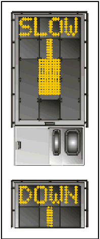 |
| 1.2.7 AZIMUTH GUIDANCE The aircraft is four meters from the stop-position. The yellow arrow indicates an aircraft to the right of the centre line, and the red flashing arrow indicates the direction to turn. | 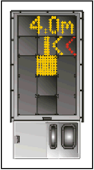 |
| 1.2.8 STOP POSITION REACHED When the correct stop-position is reached, the display will show STOP and red lights will be lit. | 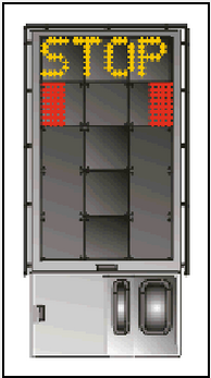 |
| 1.2.9 DOCKING COMPLETED When the aircraft has parked, OK will be displayed. | 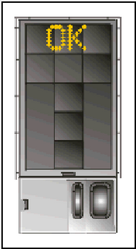 |
| 1.2.10 OVERSHOOT If the aircraft has overshot the stop - position, TOO FAR will be displayed. |  |
| 1.2.11 STOP SHORT If the aircraft is found standing still but has not reached the intended stop position, the message STOP OK will be shown after a while. |  |
| 1.2.12 WAIT If some object is blocking the view toward the approaching aircraft or the detected aircraft is lost during docking close to STOP, the display will show WAIT. The docking will continue as soon as the blocking object has disappeared or the system detects the aircraft again. THE PILOT MUST NOT PROCEED BEYOND THE BRIDGE, UNLESS THE "WAIT" MESSAGE HAS BEEN SUPERSEDED BY THE CLOSING RATE BAR. |  |
| 1.2.13 SLOW This display can be shown for two reasons:
As soon as the system detects the approaching aircraft, the vertical closing-rate bar will appear. THE PILOT MUST NOT PROCEED BEYOND THE BRIDGE; UNLESS THE CLOSING-RATE BAR IS SHOWN: |  |
| 1.2.14 AIRCRAFT VERIFICATION FAILURE During entry into the Stand, the aircraft geometry is being checked. If, for any reason, aircraft verification is not made 12 meters before the stop-position, the display will first show WAIT and make a second verification check. If this fails STOP and ID FAIL will be displayed. The text will be alternating on the upper two rows of the display. THE PILOT MUST NOT PROCEED BEYOND THE BRIDGE WITHOUT MANUAL GUIDANCE, UNLESS THE WAIT MESSAGE HAS BEEN SUPERSEDED BY THE CLOSING RATE BAR. |  |
| 1.2.15 GATE BLOCKED If an object is found blocking the view from the DGS to the planned stop position for the aircraft, the docking procedure will be halted with a WAIT and GATE BLOCK message. The docking procedure will resume as soon as the blocking object has been removed. THE PILOT MUST NOT PROCEED BEYOND THE BRIDGE WITHOUT MANUAL GUIDANCE, UNLESS THE WAIT MESSAGE HAS BEEN SUPERSEDED BY THE CLOSING RATE BAR. | 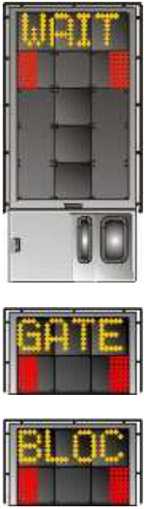 |
| 1.2.16 VIEW BLOCKED If the view towards the approaching aircraft is hindered, for instance by dirt on the window, the DGS will report a View blocked condition. Once the system is able to see the aircraft through the dirt, the message will be replaced with a closing rate display. THE PILOT MUST NOT PROCEED BEYOND THE BRIDGE WITHOUT MANUAL GUIDANCE, UNLESS THE WAIT MESSAGE HAS BEEN SUPERSEDED BY THE CLOSING RATE BAR. | 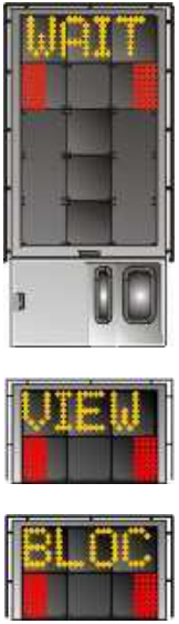 |
| 1.2.17 SBU-STOP Any unrecoverable error during the docking procedure will generate an SBU (safety back up) condition. The display will show red stop-bar and the text STOP SBU. A MANUAL BACKUP PROCEDURE WILL BE USED FOR DOCKING GUIDANCE. | 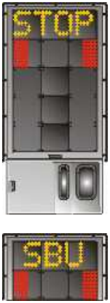 |
| 1.2.18 TOO FAST If the aircraft approaches with a speed higher than the docking system can handle, the message STOP (with red squares) and TOO FAST will be displayed. THE DOCKING SYSTEM WILL BE RE-STARTED OR THE DOCKING PROCEDURE COMPLETED BY MANUAL GUIDANCE. | 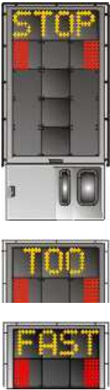 |
| 1.2.19 EMERGENCY STOP Pilots should stop the aircraft immediately when STOP is displayed. | 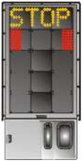 |
| 1.2.20 CHOCKS ON CHOCKS ON will be displayed, when the ground staff has put the chocks in front of the nose wheel and pressed the "Chocks On" button on the Operator Panel. | 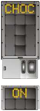 |
| 1.2.21 ERROR If a system error occurs, an error message is displayed with an error code. The code is used for maintenance purposes and is explained elsewhere. | 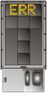 |
| 1.2.22 SYSTEM BREAKDOWN In case of a severe system failure, the display will go black except for a red stop indicator. A manual backup procedure will be used for docking guidance | 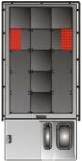 |
| 1.2.23 POWER FAILURE In case of a power failure, the display will be completely black. A manual backup procedure will be used for docking guidance. | 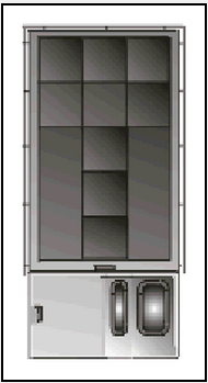 |
OTBD AD 2.24 CHARTS RELATED TO AN AERODROME
AERODROME GROUND MOVEMENT CHART - ICAO  |
AIRCRAFT PARKING / DOCKING CHART - ICAO MAIN & WESTERN APRONS |
AIRCRAFT PARKING / DOCKING CHART - ICAO EASTERN APRONS |
AERODROME LIGHTING CHART |
AERODROME OBSTACLE CHART - ICAO RWY 15/33 TYPE A |
AERODROME OBSTACLE CHART - ICAO RWY 33 OFFSET DEP TYPE A |
PRECISION APPROACH TERRAIN CHART - ICAO RWY 33 |
SID - ICAO RWY 15 BATHA 1S RNAV |
SID - ICAO RWY 15 BATHA 1S RNAV - CODING TABLE |
SID - ICAO RWY 15 ALSEM 1S / BUNDU 1S / NAMLA 1S RNAV |
SID - ICAO RWY 15 ALSEM 1S / BUNDU 1S / NAMLA 1S RNAV - CODING TABLE |
SID - ICAO RWY 15 KIROS 1S / PATOM 1S RNAV |
SID - ICAO RWY 15 KIROS 1S / PATOM 1S RNAV - CODING TABLE |
SID - ICAO RWY 15 SALWA 1S RNAV |
SID - ICAO RWY 15 SALWA 1S RNAV - CODING TABLE |
SID - ICAO RWY 15 NOPLI 1S |
SID - ICAO RWY 33 BATHA 1N RNAV |
SID - ICAO RWY 33 BATHA 1N RNAV - CODING TABLE |
SID - ICAO RWY 33 ALSEM 1N / BUNDU 1N / NAMLA 1N RNAV |
SID - ICAO RWY 33 ALSEM 1N / BUNDU 1N / NAMLA 1N RNAV - CODING TABLE |
SID - ICAO RWY 33 KIROS 1N / PATOM 1N RNAV |
SID - ICAO RWY 33 KIROS 1N / PATOM 1N RNAV - CODING TABLE |
SID - ICAO RWY 33 SALWA 1N RNAV |
SID - ICAO RWY 33 SALWA 1N RNAV - CODING TABLE |
SID - SID - ICAO RWY 33 DERNO 1N |
STAR - ICAO RWY 15 BAYAN 1S / GINTO 1S / MODED 1S RNAV |
STAR - ICAO RWY 15 BAYAN 1S / GINTO 1S / MODED 1S RNAV - CODING TABLE |
STAR - ICAO RWY 33 BAYAN 1N / GINTO 1N / MODED 1N RNAV |
STAR - ICAO RWY 33 BAYAN 1N / GINTO 1N / MODED 1N RNAV - CODING TABLE |
IAC - ICAO RWY 15 ILS |
IAC - ICAO RWY 15 VOR |
IAC - ICAO RWY 15 RNAV (GNSS) |
IAC - ICAO RWY 15 RNAV (GNSS) - CODING TABLE |
IAC - ICAO RWY 33 ILS |
IAC - ICAO RWY 33 VOR Y |
IAC - ICAO RWY 33 VOR Z |
IAC - ICAO RWY 33 RNAV (GNSS) |
IAC - ICAO RWY 33 RNAV (GNSS) - CODING TABLE |
IAC - ICAO NDB RWY 33 |
VISUAL APPROACH CHART - ICAO |
HELICOPTER CHART - ICAO |
BIRD CONCENTRATIONS |